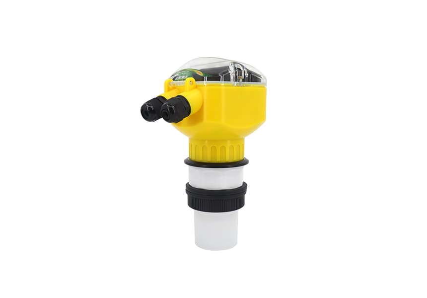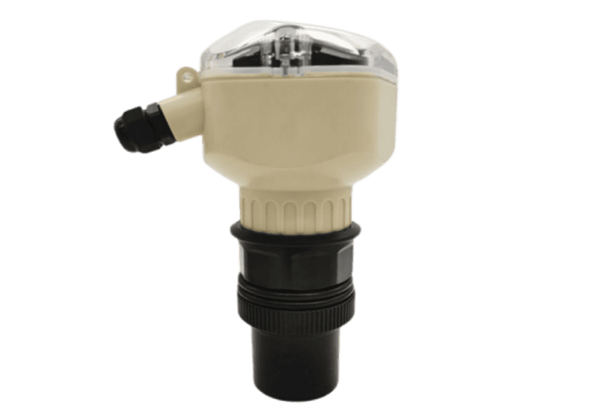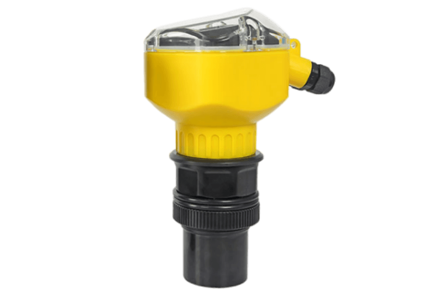
Model: Integral non-corrosion-resistant Ultrasonic Level Meter
💬 Online 9:00-18:00 (Mon-Fri) · 📋 Reply within 24h
Integral Ultrasonic Level Meter
Measuring Principle
The working principle of the ultrasonic level meter is that an ultrasonic pulse emitted by the Transducer (probe) is reflected back when it encounters the surface of the measured medium, and part of the reflected echo is received by the same Transducer and converted into an electrical signal. The ultrasonic pulse propagates at the sound velocity. The time interval from emission to reception of the ultrasonic pulse is proportional to the distance from the Transducer to the surface of the measured medium. The relationship between this distance value S, the sound velocity C, and the transmission time T can be expressed by
the formula: S=CxT/2.
Since the emitted ultrasonic pulse has a certain width, the reflected wave in a small area close to the Transducer overlaps with the emitted wave and cannot be recognized, so its distance value cannot be measured. This area is called the measurement blind zone. The size of the blind zone is related to the model of the ultrasonic level meter.
Features
Thanks to the advanced microprocessor and unique echo processing technology, the ultrasonic level meter can be applied in various complex working conditions. The "echo curve" function enables the instrument to correctly confirm the true echo under conditions with multiple echoes, obtaining accurate measurement results.
The Transducer has a built-in temperature Sensor, which enables temperature compensation of the measured value.
The ultrasonic Transducer adopts patented acoustic matching technology, allowing its transmitting power to be radiated more effectively and improving the signal strength, thereby achieving accurate measurement.
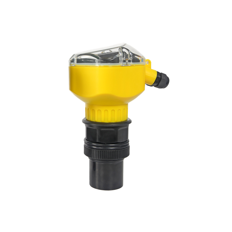
Instrument Overview
Application: liquid level measurement in various industrial and water conservancy fields
Supply voltage: 12VDC, 24VDC, 220VAC±10%
Measuring range: 2m; 5m, 10m, 15m, 20m, 25m, 30m, 35m, 40m, 45m, 50m
Process connection: determined by measuring range
Main unit housing material: ABS, PC
Sensor housing material: ABS, PVDF, PTFE
Process temperature: -25~+60℃
Process pressure: 0~3bar
Wiring system: four-wire system;
Analog signal output: 4-20mA;
Digital signal output: RS232 or RS485;
Control output: 2 relay channels
Protection Rating: IP67
Measurement accuracy: 0.5%
Display: LCD display
Sensor to main unit cable length: none
1. Product Introduction
Ultrasonic level meter (for measuring material level and liquid level) is a non-contact, high-reliability, high-cost-performance level measurement instrument that is easy to install and maintain. It can meet most level measurement requirements without contacting the medium, and is a new-generation ultrasonic level meter developed by our company through years of effort and with fully independent intellectual property rights.
2. Commissioning
Since the on-site installation environments of instruments vary, the ultrasonic level meter must know the basic conditions of the required measurement before operation, such as measuring range, zero point, full scale, and on-site working conditions, etc.
3. Main Technical Specifications
Function Energy | Integrated type | Separate type |
Measuring Range | 5m、10m、15m、20m、30m、40m、50m、60m | 5m、10m、15m、20m、30m、40m、50m、60m、70m、 |
Measuring accuracy | 0.5%-1.0% | 0.5%-1.0% |
Resolution | 3mm or 0.1%(whichever is greater) | 3mm or 0.1%(whichever is greater) |
Display Show | Chinese LCD display | Chinese LCD display |
Analog output | 4-wire 4~20mA/510Ω load 2-wiresystem 4~20mA/250Ω load | 4~20mA/510Ω load |
Relay Output | The source text is incomplete. Please provide the full Chinese product text you'd like translated.Optional: 2 sets of AC 250V/8A or DC 30V/5A, states programmable. | (Optional) Single channel: 2 groups; dual channel: 4 groups; AC 250V/8A or DC 30V/5A; status programmable. |
For electric | Standard: 24VDC Optional: 220V AC+15% 50Hz | Standard configuration: 220V AC+15% 50Hz Optional 24VDC 120mA Custom 12VDC or battery-powered |
Ambient temperature | Display instrument: -20~+60℃ Probe: -20~+80℃ | Display instrument: -20~+60℃ Probe: -20~+80℃ |
Communication | Optional RS-485, RS-232 communication (manufacturer protocol) | Optional RS-485, RS-232 communication (manufacturer protocol) |
protection rating | Display instrument IP65, probe IP68 | Display instrument IP65, probe IP68 |
Transducer cable | None | Up to 100 m, standard 10 m |
Transducer installation | Based on measuring range and transducer selection | Based on measuring range and transducer selection |
Product power consumption | Split type powered by 24V supply: 100mA without relay, 120mA with 1 relay, 145mA with 2 relays, 170mA with 3 relays, 190mA with 4 relays. Specific power consumption is as follows: Without relay: 24×100mA=2.4W; 1 relay: 24×120mA=2.9W; 2 relays: 24×145mA=3.5W; 3 relays: 24×170mA=4.1W; 4 relays: 24×190mA=4.6W; |
Product power consumption | Integrated four-wire type powered by 24V supply: 80mA without relay, 105mA with 1 relay, 130mA with 2 relays, Specific power consumption is as follows: Without relay: 24×80mA=1.9W; 1 relay: 24×105mA=2.5W; 2 relays: 24×145mA=3.1W; |
Product power consumption | Integrated two-wire type powered by 24V supply: cannot be equipped with a relay, power consumption is 30mA. Specific power consumption is as follows: Without relay: 24×30mA=0.72W; |
Note: This series of ultrasonic transducers can also be customized according to customer requirements: high-pressure resistant, high-temperature resistant, small diameter, small blind zone, and other special transducers.
4. Installation Guide
4.1 Level meter mounting dimensions
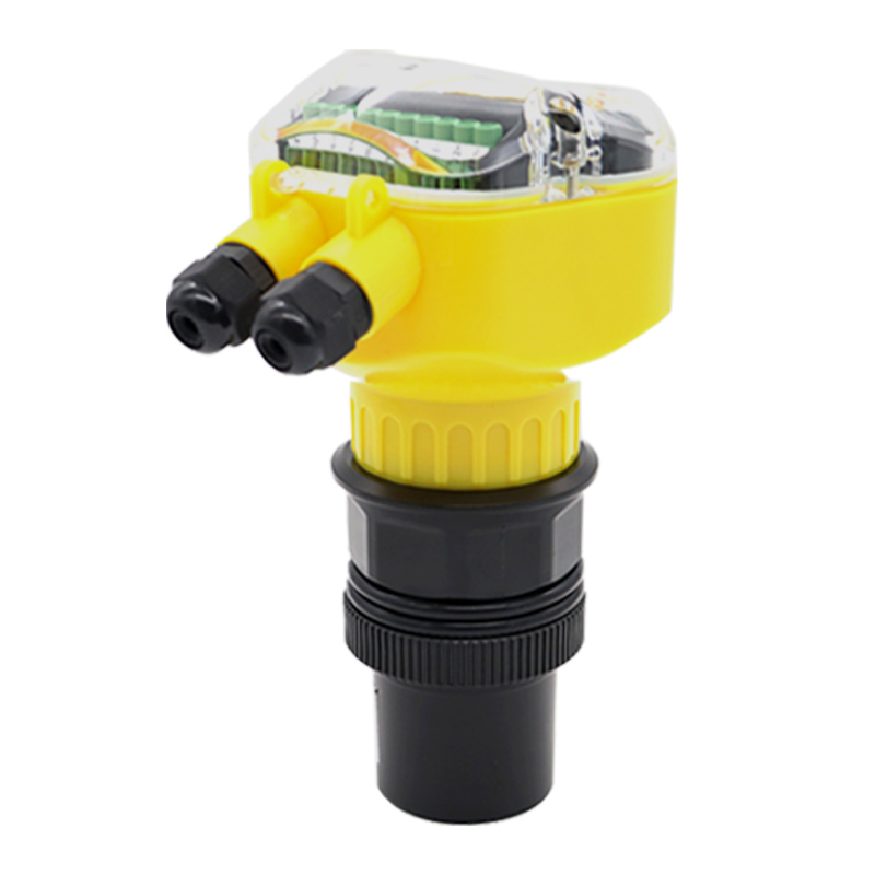
(1) Integrated ultrasonic level meter, enhanced type
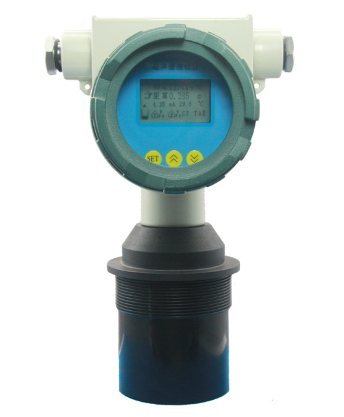
(2) Integrated ultrasonic level meter, explosion-proof type:
4.2 Installation Guide
4.2.1 Understanding Technical Terms
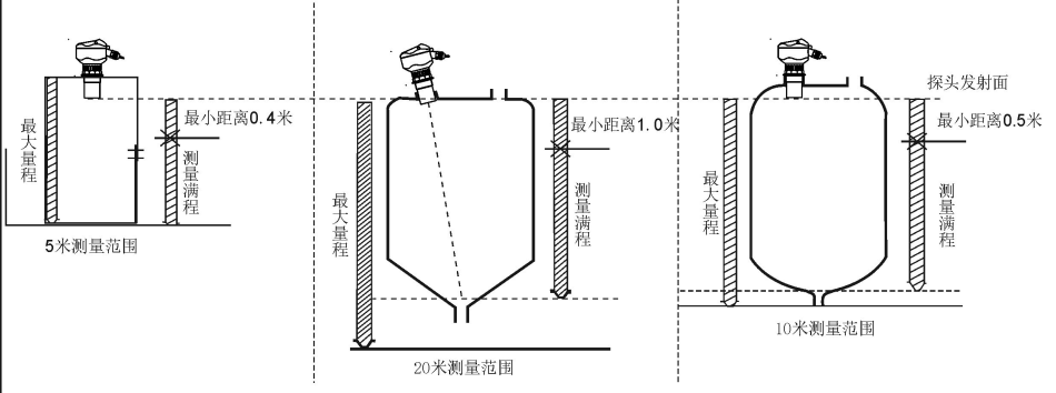
① Range: When selecting the instrument, the meaning of measuring range is very important. Please see the schematic diagram below.
② Beam angle and false echoes
The ultrasonic beam is focused by the transducer. The pulse beam is emitted like the beam of a flashlight; the farther away from the transducer, the larger the spread area.
Any object within the beam angle, such as pipes, brackets, welds, reinforcing ribs, stirring propellers, or wall-attached objects, will cause strong false echoes, especially objects closer to the transducer within the beam angle.
For example, a pipe 6 m from the transducer produces a false echo 9 times stronger than the same pipe 18 m from the transducer.
★ Try to keep the sensor axis perpendicular to the medium surface, and avoid any other objects (such as pipes and brackets) within the beam angle.
4.2.2 Measuring Range Selection
The measuring range depends on the range of the ultrasonic probe. The range of the ultrasonic probe depends on the on-site working environment, the target to be measured, temperature, etc. Based on the table below, you can select the required measuring range in meters.
Liquid surface | Attenuation multiple | Attenuation percentage | Measuring range increase multiple |
Calm | 0dB | 0% | No increase required |
Ripples | 5...10dB | 50~67% | 1x measuring range |
Large fluctuations (e.g., stirring blades) | 10...20dB | 90% | 3x measuring range |
Solid material surface | Attenuation multiple | Attenuation percentage | Measuring range increase multiple |
Hard, rough (e.g., granular rubber) | 40dB | 99% | 10x measuring range |
Soft (e.g., coal powder, cement, fly ash) | 40...60dB | 99~99.9% | Not recommended |
With dust | Attenuation multiple | Attenuation percentage | Measuring range increase multiple |
None | 0dB | 0% | No increase required |
Small amount | 5dB | 50% | 1x measuring range |
Large amount | 5...20dB | 50~90% | 3x measuring range |
With feeding | Attenuation multiple | Attenuation percentage | Measuring range increase multiple |
None | 0dB | 0% | No increase required |
Small amount | 5...10dB | 50~67% | 1x measuring range |
Large amount | 10...40dB | 67~99% | 3x measuring range |
With mist | Attenuation multiple | Attenuation percentage | Measuring range increase multiple |
None | 0dB | 0% | No increase required |
Small amount | 5...10dB | 50~67% | 1x measuring range |
Large amount | 10...20dB | 67~90% | 3x measuring range |
With steam | Attenuation multiple | Attenuation percentage | Measuring range increase multiple |
None | 0dB | 0% | No increase required |
Small amount | 5...10dB | 50~67% | 1x measuring range |
Large amount | 10...20dB | 67~90% | 3x measuring range |
Temperature difference between probe and medium surface | Attenuation multiple | Attenuation percentage | Measuring range increase multiple |
≤20℃ | 0dB | 0% | No increase required |
≤40℃ | 5...10dB | 50~67% | 1x measuring range |
≤80℃ | 10...20dB | 67~90% | 3x measuring range |
Signal attenuation calculation: if multiple conditions exist on-site, add up all these conditions to calculate the amount of signal attenuation.
· Slight filling 5...10dB
· Slight steam 5...20dB
· Temperature difference between probe and medium surface ≤40℃ 5...10dB
Total minimum 15dB, maximum 40dB.
In this case, if the actual maximum measuring range is 5m, then an ultrasonic level meter with a 50m range needs to be selected for measurement.
4.2.5 Measuring Liquids
4.2.5.1 Flat-Top Tank
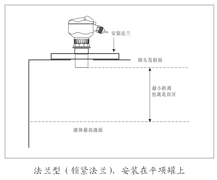
Flat-top tanks generally have a very short nozzle. The reference surface of the nozzle is the lower face of the flange. Provided that the nozzle length is ≤60mm, the nozzle inner diameter is ≥100mm, and the inner wall of the nozzle is smooth without burrs or protrusions, measurement is possible after installation when the probe's transmitting surface is 3cm below the lower face of the flange.
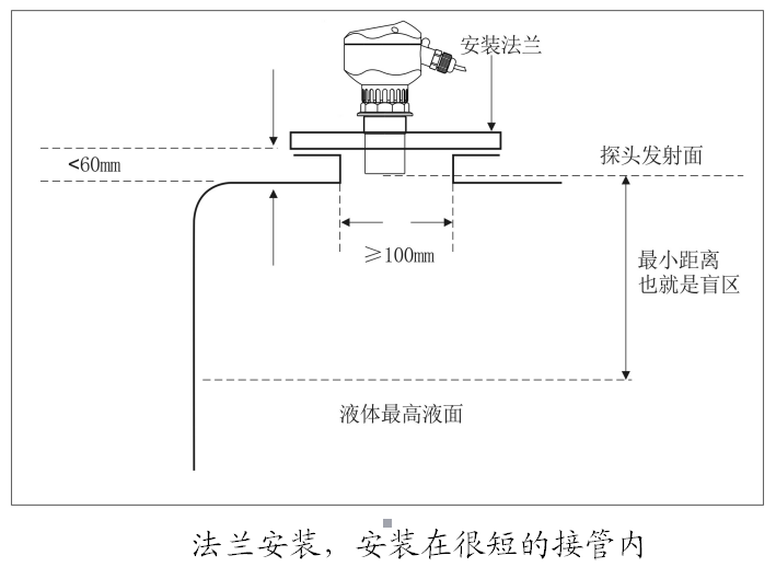
The ideal installation is to mount the instrument directly on the flat-top vessel without using a nozzle; the circular opening on the vessel is sufficient to secure the mounting flange or universal joint. The probe's transmitting surface is below the reference surface.
4.2.5.2 Arched Tank Roof
For arched tanks, the instrument should preferably not be installed at the center of the tank roof, but rather at 1/2 or 2/3 of the roof radius (provided that a certain distance from the tank wall is maintained). For ultrasonic pulses, the arched tank roof acts like a convex lens. If the probe is installed at the focal point of the convex lens, it will receive all false echoes. Therefore, installation of the sensor probe at the center of the arched tank roof should be avoided as much as possible.
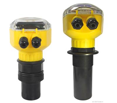
On most arched tank roofs, the length of the nozzle plus the flange is 150-180mm, while the probe of the ultrasonic level meter below the threads is not long enough (a lengthened probe can be customized by our company so that the probe's transmitting surface is below the bottom of the nozzle).
Fuzhou Dayu Electronics——Ultrasonic Level Meter, ultrasonic level meter, ultrasonic transducer,ultrasonic Doppler Flow Meterand other ultrasonic industrial instrument manufacturers.
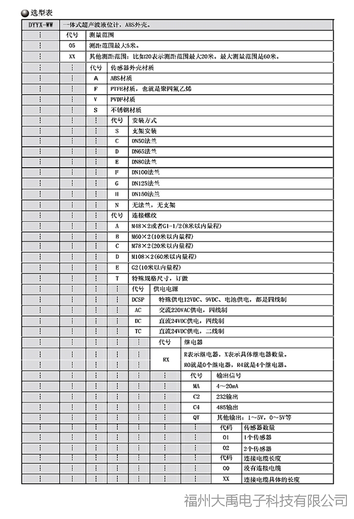
| 环境参数 | |
|---|---|
| 防护等级 | IP67 |
| 电气参数 | |
| 测量范围 | 最大5米。 |
| 测距范围 | 最大测量范围是60米。 |
| 传感器外壳材质 | ABS材质 |
| PTFE材质,也就是聚四氟乙烯 | |
| PVDF材质 | |
| 不锈钢材质 | |
| 安装方式 | 支架安装 |
| DN50法兰 | |
| DN65法兰 | |
| DN80法兰 | |
| DN100法兰 | |
| DN125法兰 | |
| DN150法兰 | |
| 无法兰,无支架 | |
| 连接螺纹 | M48×2或者G1-1/2(8米以内量程) |
| M60×2(10米以内量程) | |
| M78×2(20米以内量程) | |
| M108×2(60米以内量程) | |
| G2(10米以内量程) | |
| 供电电源 | 特殊供电12VDC、9VDC、电池供电,都是四线制 |
| 交流220VAC供电,四线制 | |
| 直流24VDC供电,四线制 | |
| 直流24VDC供电,二线制 | |
| 继电器 | R表示继电器,X表示具体继电器数量。R0就是0个继电器,R4就是4个继电器。 |
| 输出信号 | 4~20mA |
| 232输出 | |
| 485输出 | |
| 其他输出:1~5V,0~5V等 | |
| 传感器数量 | 1个传感器 |
| 2个传感器 | |
| 连接电缆长度 | 没有连接电缆 |
| 连接电缆具体的长度 | |
Send us your working conditions — engineers reply with selection advice and pricing within 24 hours.
Online 9:00-18:00 (Mon-Fri)