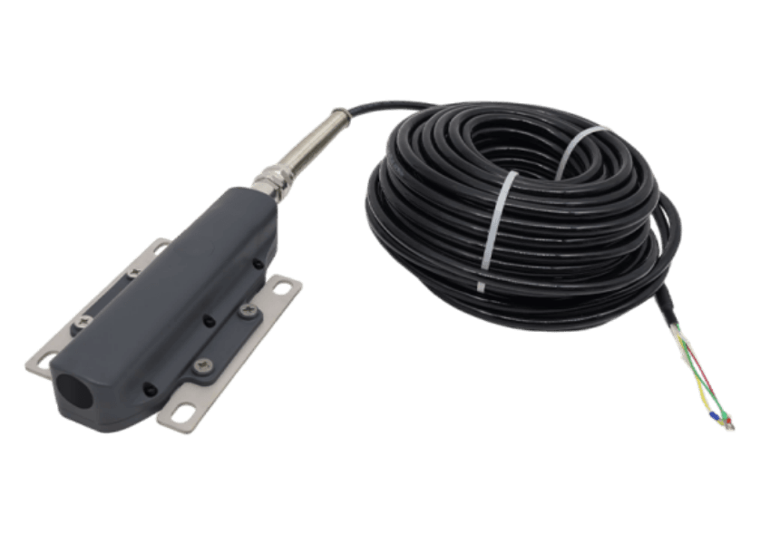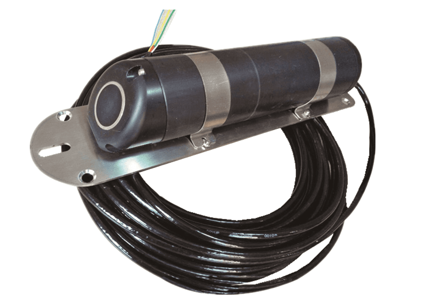
Model: Single-beam acoustic Doppler current profiler
💬 Online 9:00-18:00 (Mon-Fri) · 📋 Reply within 24h
ADCP stands for Acoustic Doppler Current Profilers. The Acoustic Doppler Current Profiler is a flow measurement device developed in the early 1980s. ADCP can directly measure the velocity profile of a cross-section, without disturbing the flow field, with short testing time and a wide velocity measurement range. It is currently used for flow field structure surveys in marine and estuarine environments, velocity and discharge measurements, etc.
I. Product Photos and Introduction
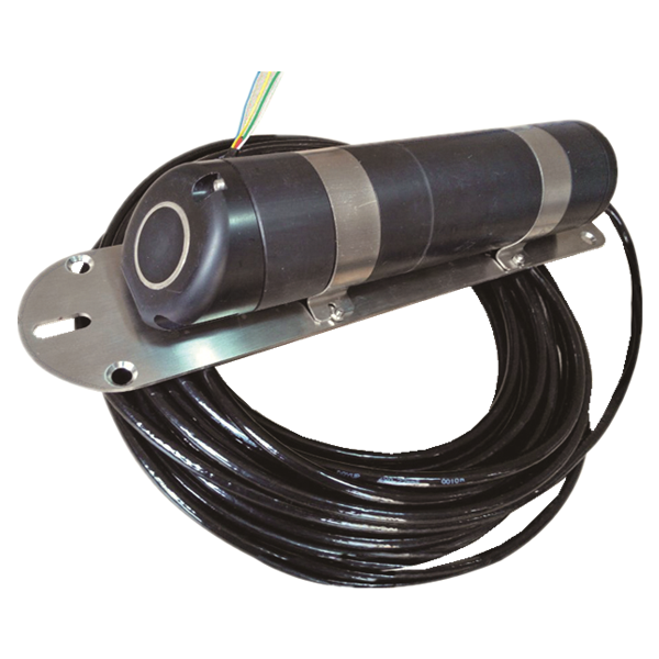
The product measures flow velocity based on the ultrasonic Doppler effect. It emits an ultrasonic pulse into the water, receives reflected echo signals from particles and bubbles in the water, calculates velocity changes based on the frequency shift of the echo signals, and determines velocity stratification based on the time sequence of the echo signals. It can also measure water level via a pressure sensor and water temperature via a temperature sensor.
This single-beamAcoustic Doppler Current ProfilerIt is typically installed on the bottom. In this way, it can remotely measure the flow velocity at various water layers by transmitting ultrasonic pulses. At the same time, it can output the test time (year/month/day/hour/minute/second), roll angle, pitch angle, and temperature value, facilitating correction to obtain accurate flow velocity.
The housing is made of POM plastic (also known as polyacetal, a crystalline thermoplastic plastic). It has a distinct melting point of 165~175°C, and its properties are closest to metal, so it is commonly called plastic steel. It adopts a deep-sea pressure-resistant design for effective waterproof sealing.
* Uses Modbus communication protocol and communicates via RS485 bus.
* Host computer for data acquisition. Supports one-to-many usage (one host computer connects to multiple slave devices).
* Simple product communication commands.
* Underwater sensor equipment is easy to install. With a metal base fixing device, installation is simple.
* All-electronic design with no mechanical parts. Offers accurate and stable measurement, high reliability, and strong anti-interference capability.
* Wide range of applications. Can be used in various water environments from tap water to Yellow River water.
II. Product Principle
Single-beam Acoustic Doppler Current Profiler principle: When the ultrasonic sound source and the observer move relative to each other, the frequency received by the observer differs from the frequency of the ultrasonic sound source. Therefore, small particles and bubbles moving with the water relative to the ultrasonic transducer also cause a change in the frequency received by the transducer, and this change increases with the speed of suspended movement in the water. By measuring the Doppler shift, the water flow velocity is obtained.
It is mainly used in irrigation open channels, municipal sewage pipes, hydrological watersheds, and other applications, especially suitable for water areas with depths from over 0.5 meters to several meters. In regular pipes and channels, the pressure sensor on the current meter measures the water depth, and the ultrasonic sensor measures the flow velocity at each layer; the flow rate can then be conveniently calculated using the background calculation software.
III. Product Technical Specifications
Table 1 Measurement Specifications
Content | Model 1000KHZ | Model 2000KHZ |
Frequency | 1000KHZ | 2000KHZ |
Maximum measuring range | 16m | 8m |
Cell size | 0.25m~1m | 0.125m~0.5m |
Number of cells | 32 | 32 |
Flow measurement range | 0.02 m/S~8m/S | 0.01 m/S~6m/S |
Flow measurement accuracy | 0.5%+0.5cm/S | 0.5%+0.5cm/S |
Operating depth | 50m | 50m |
Measurement blind zone | 0.50m | 0.30m |
Table 2 Performance Specifications
Electrical specifications | Range | Remarks |
Operating voltage(V) | 12V~15V | DC |
Current consumption(mA) | <=150 | 12Vpower supply |
Data update period(S) | 30Second | Default |
Operating temperature (℃) | 0~60℃ |
4. Installation Requirements
The acoustic Doppler velocity profiler should be installed at the downstream end of a straight reach of a channel with a fixed cross-section. The longer the straight reach, the higher the measurement accuracy, and there must be no flow-blocking obstructions (such as sluice gates, weirs, etc.) within 10 m to ensure uniform and stable flow conditions in front of the probe. The installation position should avoid the vicinity of the banks as much as possible; place the probe horizontally at the midpoint between the two banks, and vertically on the bottom (provided the waterway has no silt; if it does, the installation position should be above the silt). As shown in Figure 1, when there is sediment deposition, aquatic weed growth, or rolling cobbles at the channel bottom, the installation position can be raised to avoid sediment and weeds covering the probe or cobbles impacting the probe. The specific height of the acoustic Doppler velocity profiler above the channel bottom should preferably be 5 cm, depending on the minimum water level for flow measurement. When the channel water is deep and has a certain minimum water level, for installation convenience, simply install the probe at a depth of 0.5 times the minimum water level.
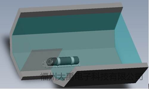
Figure 3 Doppler Velocity Profiler Installation
The host computer is usually installed on a utility pole on the bank or in an equipment room, as shown in Figure 2. The function of the host computer is to control the measurement interval of the Doppler velocity profiler through settings. Generally, to save power, the Doppler velocity profiler is powered on only during data acquisition and a measurement command is sent, and it is powered off between two measurement intervals. The flow rate can be calculated from the measured water level and velocity data. Alternatively, the raw velocity and water level information can be directly time-stamped and stored, or transmitted remotely via SMS, GPRS, or other means.
During installation, the air-vent cable should be led out of the water along the channel bottom and wall in the downstream direction of the flow meter. It is best to protect it with a PVC pipe or stainless steel pipe and fix it along the route. When an arm-type bracket is used to fix the probe, the air-vent cable can be led out of the water along the hollow steel tube of the bracket.
The Doppler velocity profiler comes with a 20 m air-vent cable. In the middle of this cable there is an air tube used to balance atmospheric pressure; the air tube has an outer diameter of about 2 mm and an inner diameter of about 1 mm. Therefore, be careful not to bend or kink it. After the communication cable is led out of the water, it can be connected to a common cable. At this time, the opening of the vent tube should face downward and be protected with breathable tape to prevent water and foreign matter from entering the vent tube.
The four-core wires in the air-vent cable are generally green (+12V), white (GND), blue (RS485A), and yellow (RS485B). (Any changes will be notified to the user at the time of delivery.)
The 12V power supply for the Doppler velocity profiler can come from a battery or solar power, and of course also from the mains. Currently, there are two main types of power supplies that convert 220V AC mains to 12V: one is the linear power supply, i.e., the type using a power transformer; the other is the switching power supply, which is the most popular now. When selecting a power supply, try to use a linear power supply, because the brands of switching power supplies on the market are mixed, and some have large ripple, which does not meet relevant EMC standards and can easily interfere with ultrasonic measurement.
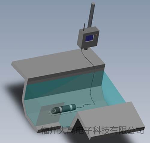
Figure 4 Measurement System Installation Diagram
The Doppler velocity profiler comes with a 2.5 mm thick stainless steel plate as the mounting base plate. The specific mounting hole dimensions are shown in Figure 5.
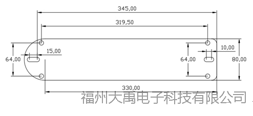
Figure 5 Base Plate Hole Positions
5. Precautions
5.1 The air-vent cable contains an air tube inside, so it must not be bent excessively to prevent breakage. Never use the air-vent cable as a tether for the flow meter, or drag the Doppler velocity profiler by the air-vent cable.
5.2 The air tube inside the air-vent cable communicates with the circuit board inside the probe. It must not get water inside. During installation, the opening at the end of the air tube should face downward to prevent moisture from condensing and flowing along the tube wall into the probe circuit.
5.3 When the air-vent cable is led out of the water from the probe, it should be protected with a PVC pipe as much as possible, and fixed along the route or routed through the bracket tube, so as to avoid tension caused by direct hydraulic impact. Especially in channels with abundant aquatic weeds, when weeds get caught on the cable, a large tension can be generated and may break the air-vent cable.
5.4 The circular ultrasonic transducer at the front of the probe must not be impacted or scratched.
5.5 The wiring between the host computer (totalizer) and the probe must be correctly connected; otherwise, the instrument may be damaged.
5.6 The instrument probe should be protected from prolonged exposure to direct sunlight to avoid malfunctions caused by excessive temperature (the probe temperature must not exceed 70℃).
5.7 In areas with high sediment concentration, when using an Acoustic Doppler Current Profiler (ADCP), periodically clean the silt from the ultrasonic transducer and pressure sensor to prevent the silt from clogging the pressure sensor.
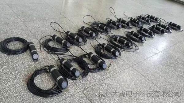
Fuzhou Dayu Electronics — ADCP Acoustic Doppler Current Profiler manufacturer, is your considerate product consultant.
For more details, please call the hotline: 0591-28082552 or add corporate QQ: 2187169532 Fuzhou Dayu Electronic Technology Co., Ltd. will serve you wholeheartedly!
Send us your working conditions — engineers reply with selection advice and pricing within 24 hours.
Online 9:00-18:00 (Mon-Fri)