Ultrasonic Clamp-on Flowmeter [Dayu Electronics]
Ultrasonic Clamp-on Flowmeter is suitable for measuring liquid flow in full pipes with pipe diameters from DN15 to DN6000. Different sensor models are selected based on pipe size.
Sensor Type | Applicable Pipe Diameter | Standard Temperature Range | High-Temperature Range |
Small Sensor | DN15~100 | -40~90℃ | -30~160℃ |
Medium Sensor | DN50~700 | -40~90℃ | -30~160℃ |
Large Sensor | DN300~6000 | -40~90℃ | -30~160℃ |
The clamp-on flowmeter is applicable to pipes made of carbon steel, cast iron, stainless steel, PVC, PPR, PE, and other materials without lining and free from internal rust.
Measurable medium: Water
1. Selecting the Measurement Point
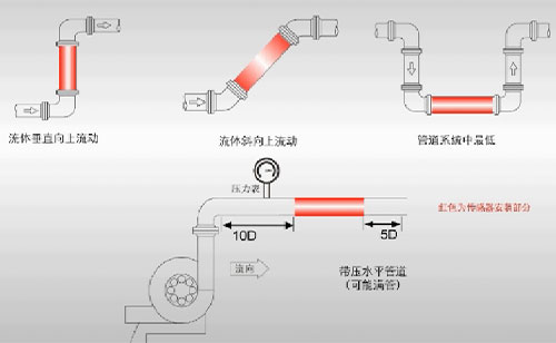
Try to satisfy the straight-pipe requirements: at least 10D upstream from the nearest elbow and 5D downstream. If this cannot be met, install the transducers as close as possible to the midpoint between the upstream and downstream sections. (D is the outer diameter of the pipe.)
Below are recommendations for selecting the installation section:
2. Locating the Installation Point
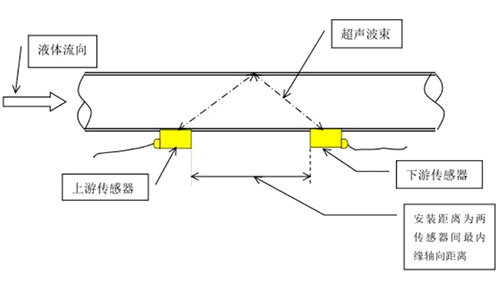
If the pipe has an insulation layer, remove part of it according to the required mounting distance and method. After positioning, ensure that both sensors are on the same axial plane. Always install the sensors on the sides of the pipe, not on the top or bottom (as shown).
1. Top view of V-method installation for clamp-on sensors (recommended when the outer diameter is less than 200 mm)
Field installation photo 1 for V-method (vertical upward flow section)
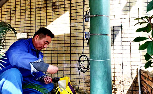
Field installation photo 2 for V-method (horizontal flow section)
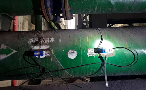
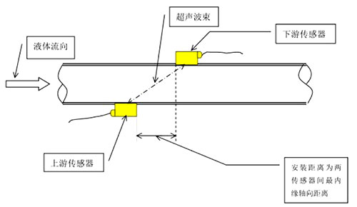
2. Top view of Z-method installation for clamp-on sensors (recommended when the outer diameter is greater than 200 mm)
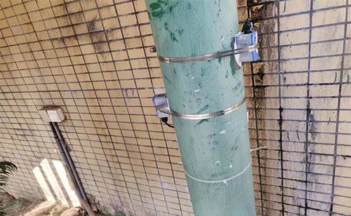
Field installation photo 1 for Z-method (vertical upward flow section)
Field installation photo 2 for Z-method (horizontal flow section)
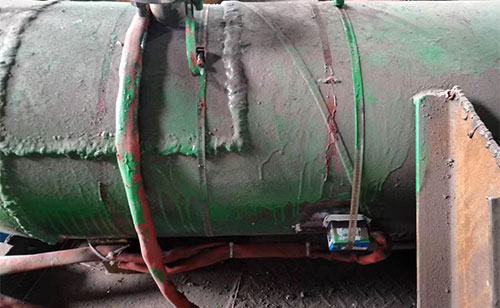
In actual measurement, considering that air bubbles may accumulate at the top of the pipe and sediment at the bottom, the transducers should be mounted on the horizontal sides of the pipe. If space is limited, the sensors may be installed vertically or at an angle, provided that the pipe remains full of liquid and free of air bubbles.
3. Preparing the Installation Point
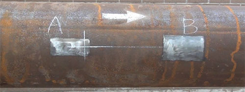
For metal pipes, polish the installation area with an angle grinder or flat file until the surface is smooth and clean. Create a square area approximately 1.5 times the area of the sensor bottom to allow movement for optimizing the signal. (For PVC pipes, simply wipe clean; no grinding is needed.) After polishing, the surface should be shiny, free of ridges, and free of rust. See below:
4. Transducer Installation and Adjustment
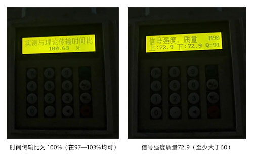
Before mounting, evenly apply 5-10 mm of couplant (grease is sufficient; use molybdenum disulfide above 110°C) to the bottom of the transducers. Press the transducers firmly against the polished areas of the pipe (ensuring good acoustic coupling with no air bubbles, sand, or other impurities) and slowly move them until the time transmission ratio reaches 100% (acceptable range: 97-103%). The signal strength and quality should both be greater than 60 (the higher, the better). Mark the transducer positions, wipe off the couplant, and replace it with the supplied sealant. Fill the sensor housing with sealant. Secure the sensors with the provided wire spring, stretching it to about twice its original length.