
Twelve Major Issues in the Use of Rail Inspection Transducers (Part 1) [Dayu Electronics]
To ensure stable and safe train operation, routine defect inspection of the rail surface has become an important task in railway maintenance. Ultrasonic monitoring of rails offers advantages such as fast inspection speed and high precision. During ultrasonic inspection, the transmitting and receiving transducers need to be placed on both sides of the rail. When communicating with companies that use rail inspection transducers to develop rail break detection equipment, our company received the following feedback.
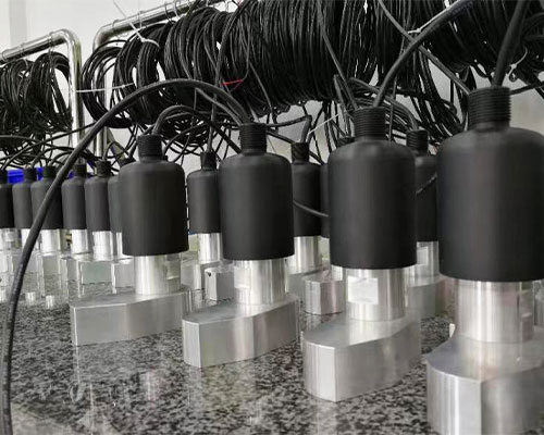
1. The shield wire of the transducer must not be connected to the ceramic element.
In practice, the rail is electrically live. When the ceramic element is broken down, the positive and negative cables of the transducer become conductive. If the shield wire is connected to the ceramic element, and since the shield wire is connected to the railway grounding grid, the current on the rail will be connected to the earth, causing problems with the rail current, which serves specific purposes for the railway authority.
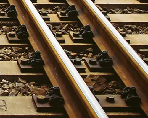
2. Couplant issues.
When medical petroleum jelly is used as a couplant in environments below 0°C, the moisture in the jelly can separate and freeze on the rail, causing the coupling to fail. As a result, most of the signals emitted by the transducer cannot enter the rail, leading to unnecessary loss. Using silicone gel as a couplant works better. Ordinary liquid couplants, when applied at room temperature, gradually lose their coupling effect after a short period.
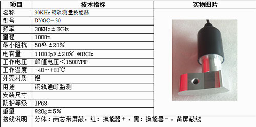
Field requirement: The couplant should be applied once and remain effective for several years without failure. Improvement method: Use a 2–5 mm silicone pad between the transducer and the rail as the couplant, and firmly secure the transducer to the rail with a clamp. No liquid couplant is applied.
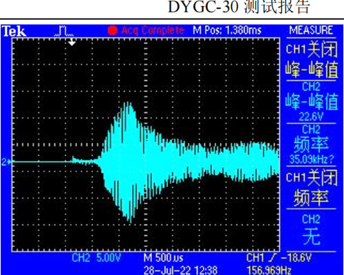
3. The transmitted signal can propagate to the other rail.
A track consists of two rails, one on each side. Experiments show that when a pulse is emitted by the transmitting transducer on the left rail, the receiving transducer and circuit on the right rail can clearly detect the signal. Even without the transmitting transducer on the right rail being active, the receiving transducer and circuit on the right rail can still detect the signal from the left rail's transmitter, though the signal is weaker than that received on the left rail. The cause may be conduction through the sleepers. Since both rails may transmit and receive simultaneously, this issue can be resolved by using transducers with different frequencies on each side. The frequency difference should be more than 5 kHz to avoid interference.
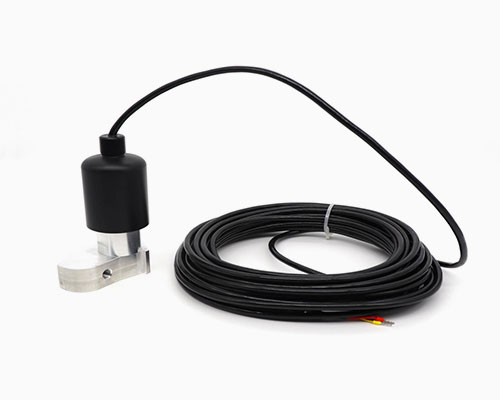
4. Circuit noise issues
The signal received by the existing receiving circuit, after passing through a logarithmic amplifier, can reach about 1000 mV, but the circuit's background noise is 400 mV or more, which is clearly too high. Possible causes include: ① The circuit before the logarithmic amplifier does not filter out noise; a narrowband filter can be added before the logarithmic amplifier. For example, if the transducer transmits a 30 kHz signal, the filtered bandwidth should be limited to 26–35 kHz. ② The DC-DC power chip selected for the power supply has excessive noise; a DC-DC chip with isolation should be used, or a low-ripple power chip such as those from LINT.
5. What frequency should be used for rail transducers?
If the rail length between two transducers is 800–1200 meters, and the circuit is properly designed, a transducer frequency of 23–35 kHz is recommended.
6. What transmit voltage (VPP) should be used for rail transducers?