
Ultrasonic Doppler Flowmeter for Flow Distribution in Agricultural Irrigation Channels
In Wenwu Village, Xinjin County, Chengdu City, Sichuan Province, ultrasonic Doppler flowmeters were selected for two measurement points on the main and branch irrigation canals to measure flow velocity, instantaneous flow rate, cumulative flow, water level, and water temperature. Our company will provide a reasonable installation scheme based on the ultrasonic Doppler flowmeter installation principles combined with on-site conditions, enabling the owner to control channel water flow for zoned farmland irrigation.
I. Selection of Installation Points:
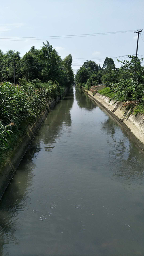
(Main canal: water surface width approx. 8.8m, riverbed width approx. 6m, height approx. 2.5m, measured water depth 1.15m. Since there is a sluice gate 800m downstream, the minimum water level is unknown.)
The main canal has sluice gates at both the upstream and downstream ends, with approximately 800m of straight canal in between. According to the ultrasonic Doppler flowmeter installation principles: upstream of the sluice gate on a non-sloped section, there must be a straight channel section 10 times the channel width, and downstream there must be a straight channel section 5 times the channel width. Therefore, the installation point for the main canal is located approximately 80m downstream of the sluice gate where the water flow is stable and free from turbulence.
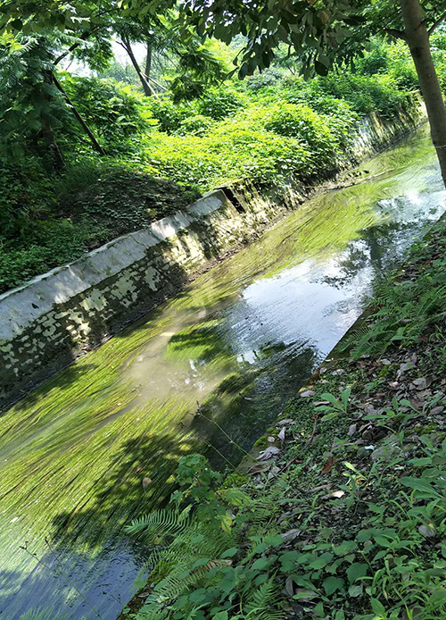
(Branch canal: water surface width approx. 5m, canal bottom width approx. 4m, height approx. 1.6m, measured water depth 0.25m)
The initial installation point for the branch canal is selected at 50m downstream of the sluice gate where the water flow is stable and free from turbulence.
II. Sensor Installation Principles and Installation Diagrams:
1. Determining the Installation Height of the Sensor:
The ideal height from the probe to the canal bottom is 100mm–250mm. The sensor should be installed as close to the canal bottom as possible. If there is significant sediment, silt, aquatic weeds, or rolling stones at the canal bottom, the installation position can be raised to prevent the probe from being covered by sediment or aquatic weeds, or damaged by stones impacting the probe.
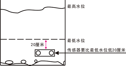
The minimum water level must be more than 20cm above the sensor
The main canal meets the minimum water level requirement and can be installed at 10cm above the sediment level. For the branch canal, since the current water level is only 25cm, it only satisfies the sensor installation height requirement. Therefore, the branch canal requires cleaning of silt and aquatic weeds from the canal bottom within 10m before and after the installation point to lower the sensor installation position.
2. Selection of Horizontal Installation Position:
Trapezoidal canal installation: The sensor is installed at the junction of the slope and the bottom edge, also known as the "slope toe." Additionally, the sensor must be installed at least 20cm below the minimum water level.
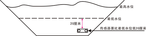
Installation position requirements for trapezoidal canals
However, based on the on-site canal conditions, the sensor should also be installed at 15-20% of the canal width from the side.
3. The Sensor Must Face Directly into the Water Flow Direction:
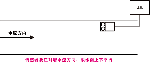
Horizontal installation requirements for the sensor
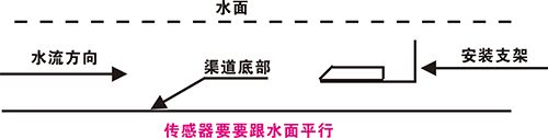
Horizontal installation requirements for the sensor
To avoid non-power-related issues with the sensor, such as the inability to obtain data normally due to debris or floating objects blocking the sensor on-site, a grating screen can be installed on the upstream section of the canal to filter out upstream debris or floating objects.
4. Main Canal Installation Diagram:
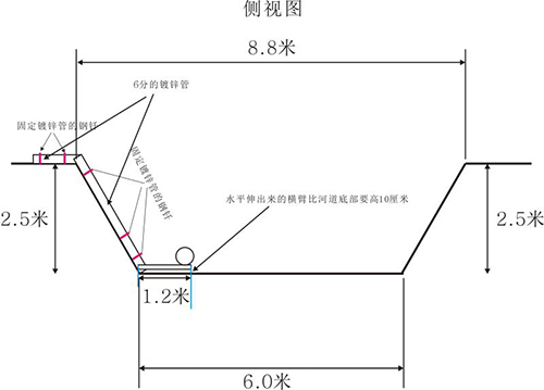
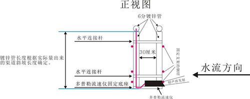
5. Branch Canal Installation Diagram:
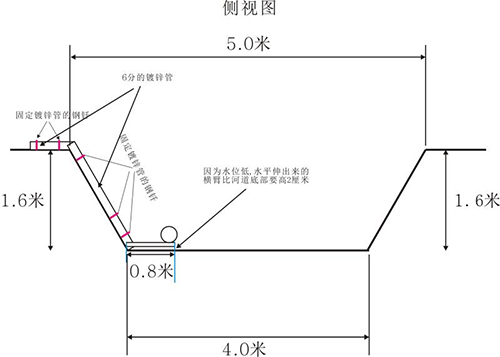
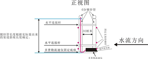
6. Bracket Fabrication and Actual Installation Completion Photos:
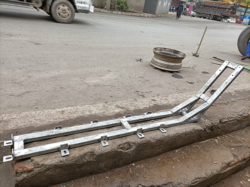
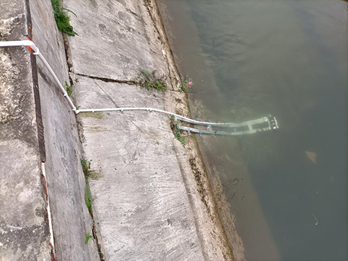
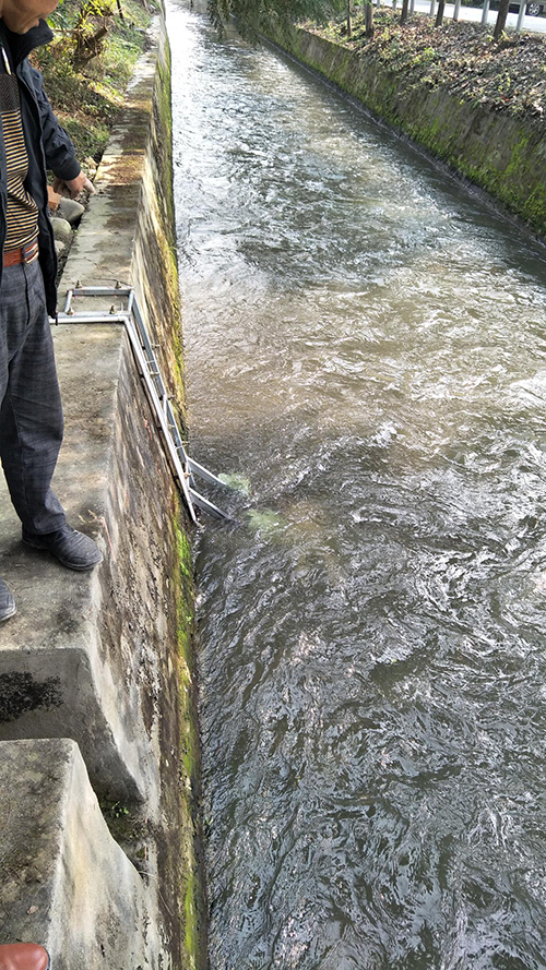
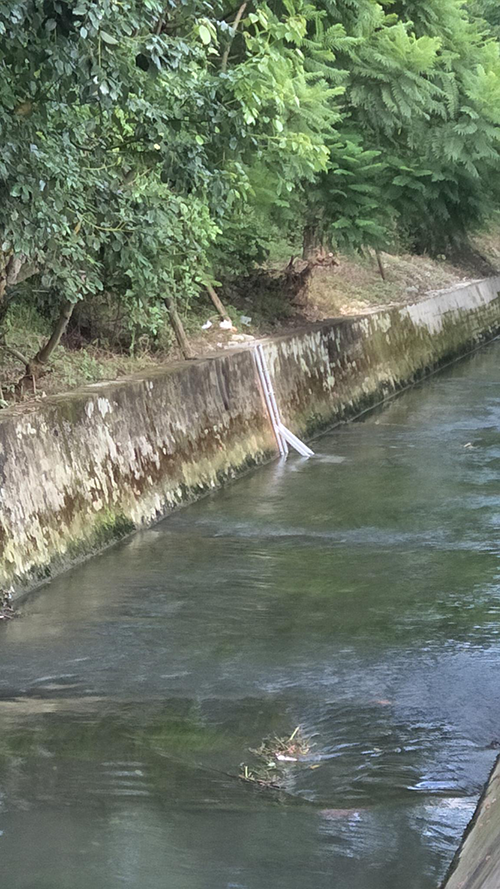
III. Installation Auxiliary Materials List:
Applicable Canal | Material Name | Length | Quantity |
Main Ca nal | 50mm galvanized pipe | 0.5m | 2 |
50mm galvanized pipe | 3m | 2 | |
50mm galvanized pipe | 1.2m | 2 | |
3/4-inch galvanized steel pipe | 0.3m | 7 | |
Fixing screws | 10 | ||
Steel stakes | 16cm or longer | 10 | |
Fixing steel plate | 20*70cm | 1 | |
Cable protection conduit | 90m | 1 | |
Branch Ca nal | 50mm galvanized pipe | 0.5m | 2 |
50mm galvanized pipe | 2m | 2 | |
50mm galvanized pipe | 0.8m | 2 | |
3/4-inch galvanized steel pipe | 0.3m | 7 | |
Fixing screws | 10 | ||
Steel stakes | 16cm or longer | 10 | |
Fixing steel plate | 20*70cm | 1 | |
Cable protection conduit | 60m | 1 |
IV. Post-Installation Maintenance Recommendations for the Ultrasonic Doppler Flowmeter:
Since the measurement principle of the ultrasonic Doppler sensor is based on two transducers—one transmitting and one receiving—the two transducers of the Doppler flowmeter must be kept clean, with no obstruction or attachments at the transmitting end of the transducer. Therefore, the user should regularly inspect or clean the measurement point every two weeks or once a month. Alternatively, troubleshooting and cleaning of the sensor transmitting section can be performed after the backend management system shows no data.
The branch canal requires regular inspection and cleaning of sediment at the canal bottom to prevent silt from blocking the transducers and causing measurement failure.