
Ultrasonic Doppler Velocimeter
Ultrasonic Doppler Velocimeter
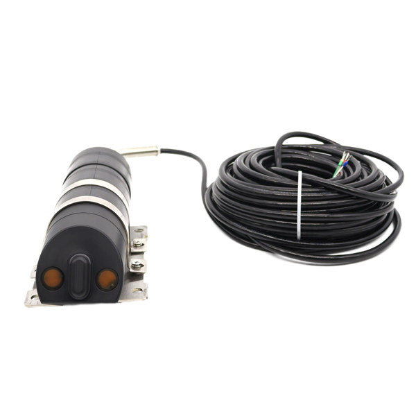
Measurement Principle
The ultrasonic Doppler velocimeter operates by placing an ultrasonic sensor in the target channel or river. The sensor emits ultrasonic waves into the water, and based on the intensity of the reflected ultrasonic signals and other parameters, the water flow velocity can be calculated. This data is transmitted to the user via built-in hardware and software. It is widely used for measuring water flow velocity in pipes, channels, or rivers.
Typical applicable environments include:
· Flood disaster monitoring
· Sewage discharge
· Natural rivers and streams
· Municipal water supply and drainage
· Water loss/infiltration monitoring
· Irrigation flow monitoring
· Estuary and tidal research
· Fisheries/water conservancy
· Coastal erosion research
· Culvert flow monitoring
· Road drainage monitoring
· Canal flow research
· River flow monitoring
Battery power supply systems can be provided upon request for areas where power supply is inconvenient.
GPRS wireless transmission kits can be provided upon request for viewing field data on a backend server.
Product Features
I. Product and Technical Parameters
1.1 Flow velocity measurement principle: Uses the Doppler shift physical principle to measure water flow velocity.
What is the Doppler effect (Doppler shift):
Ultrasonic waves emitted by a source are received and reflected by another receiving body. If the sound source is moving relative to the receiving body, the frequency of the sound waves received by the receiving body will differ from the emission frequency of the sound source.
If the relative distance between two objects is decreasing, the received frequency will increase.
If the relative distance between two objects is increasing, the received frequency will decrease.
Such Doppler effects are common in daily life. For example, when you hear the whistle of an oncoming train or the siren of a police car approaching (a sound source), the sound appears higher in frequency; when the train or police car moves away from you, the sound becomes lower.
The specific flow velocity is calculated based on the difference between the transmitted ultrasonic frequency and the received ultrasonic frequency.
Technical Parameters
Structure: Split type
Measurement types: Flow velocity, water depth (water temperature measurement is an optional feature)
Application: Online measurement
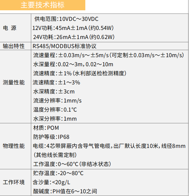
pH range: pH value between 6 and 10
Liquid pressure requirement: 1 standard atmosphere under natural environmental conditions
Note: 1. Flow velocity cannot be measured when water is frozen or near freezing point.
2. The default maximum water depth shall not exceed 10 meters. If depths greater than 10 meters are required, the manufacturer must be clearly notified before ordering.
1.4 Measurement Status and Wiring
Data is calculated 60 seconds after power-on, and subsequently updated every 10–15 seconds. (Note: The data is not actively uploaded; it is passively uploaded — the host computer must send a query command to retrieve the measurement data.)
The cable is a four-core shielded cable: two wires for power and two wires for the 485 signal.
Power wires: red is positive, white is negative; blue is 485A, yellow is 485B.
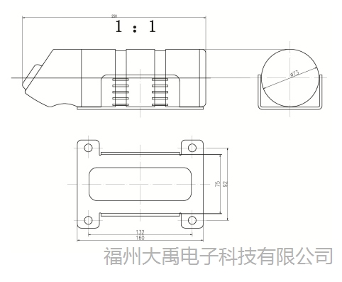
Product Structure Diagram
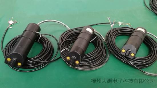
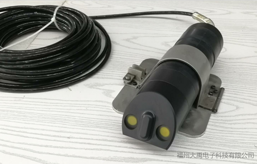
Product Photos
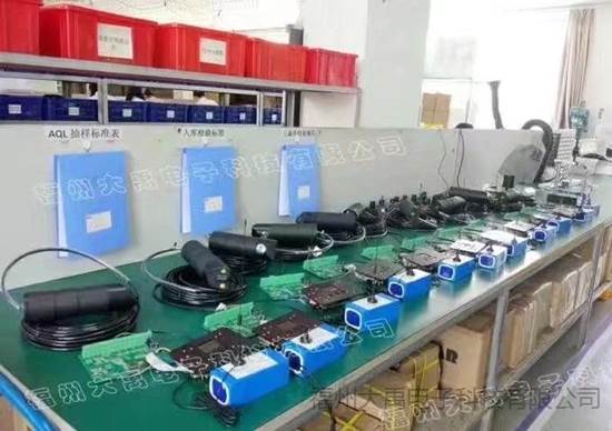
On-site voltage stabilization check
The ultrasonic Doppler velocimeter sensor has a stainless steel mounting base. The four holes on the base are used for securing it to the ground, and the side opening is used for securing the sensor with a hose clamp.
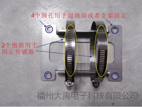
Sensor Mounting Base Diagram
II. Product Installation
2.1 Selection of Installation Location
Choose a location with steady water flow for measurement.
In areas with unsteady water flow, turbulent flow is common in most cases. Under turbulent conditions, the measured flow velocity fluctuates, is unstable, and the error can be significant.
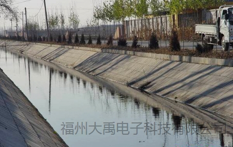
Figure 2.1.1 Select a channel section with steady flow velocity for installation
2.2 Requirements for Upstream and Downstream Channels
Under ideal conditions, the flowmeter installation location should have a straight channel section 10 times the channel width upstream and 3 times the channel width downstream.
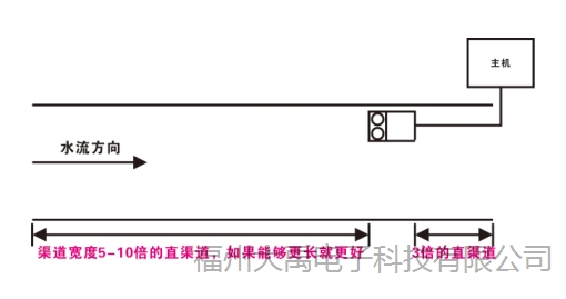
Figure 2.2.1 Requirements for upstream and downstream straight channel sections
UpstreamThe longer the straight channel section, the better. The longer it is, the steadier the water flow, and the closer the velocity measurement will be to the actual flow velocity. Additionally, there must be no obstructions in this section, such as gates, weirs, or flumes, to ensure stable flow without turbulence in front of the sensor.
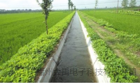
Figure 2.2.2 The longer the upstream straight channel section, the better
If the upstream10times the channel width straight section cannot be achieved, at least the channel width5times is required, and it cannot be less than5times.
Example: If a rectangular channel has a width of 2 meters, what should be the lengths of the upstream and downstream straight channel sections at the sensor installation location?
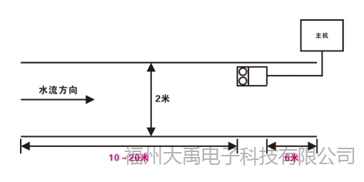
Figure 2.2.3 Upstream and downstream straight channel requirements for a 2-meter-wide channel
Example: If a trapezoidal channel has a top width of 5 meters, a bottom width of 2 meters, and a height of 2 meters, how should the channel width be determined?
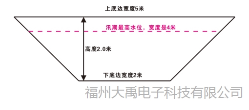
Figure 2.2.4 How to determine the width of a trapezoidal channel
The width of the channel shall be determined by the width at the highest flood season water level. If the flood season water level exceeds the highest point of the trapezoidal channel, then the top width of the trapezoidal channel shall be used as the standard.
If the width at the highest flood season water level is 4 meters, the upstream straight channel section should be 20–40 meters and the downstream straight channel section should be 12 meters at the installation location.
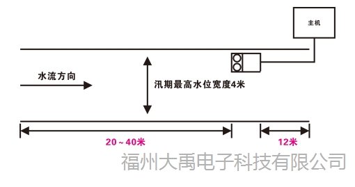
Figure 2.2.5 Calculation of upstream and downstream straight channel lengths for a trapezoidal channel
2.3 Requirements for Installation Downstream of a Gate
If installed downstream of a gate, special attention must be paid to observing the water surface condition to check whether it is steady.
Figure 2.3.1 Downstream of a gate
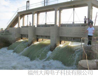
If the distance between the sensor installation location and the gate has already reached 10 times the channel width, but the water surface is still unsteady, the distance between the sensor and the gate needs to be increased until the water flow becomes steady.
Within a certain distance downstream of a gate, there is generally a reinforced concrete channel, which is relatively regular. Many sites choose a location close to the downstream side of the gate for installation convenience. However, water flow at such locations is typically turbulent and chaotic, and the measured data can differ significantly from the actual flow velocity.
Such locations are not suitable for installation.
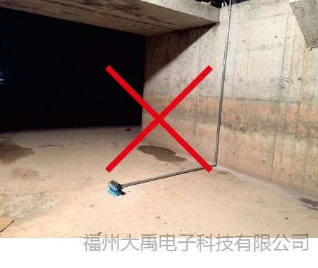
Figure 2.3.2 Incorrect installation location — installed at the gate outlet
2.4 Selection of Installation Height
First, determine the low-water season water level. The sensor should be installed 10 cm lower than the lowest water level.
The sensor should be installed as close to the channel bottom as possible. If the channel bottom has significant sediment, silt, aquatic weeds, or rolling stones, the installation position can be raised to prevent the probe from being covered by sediment or weeds, or being struck by stones.
The ideal height of the probe from the channel bottom is 100 mm–250 mm, depending on the lowest water level of the channel.
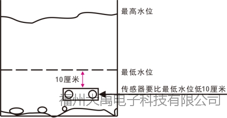
Figure 2.4.1 The sensor should be installed 10 cm lower than the lowest water level
When the channel water level is relatively high and the lowest water level is also relatively high, the probe can be installed at 0.5 times the depth below the lowest water level for installation convenience.
Example: If the lowest water level is 1.00 meter, the sensor can be installed at 0.50 meters above the channel bottom.
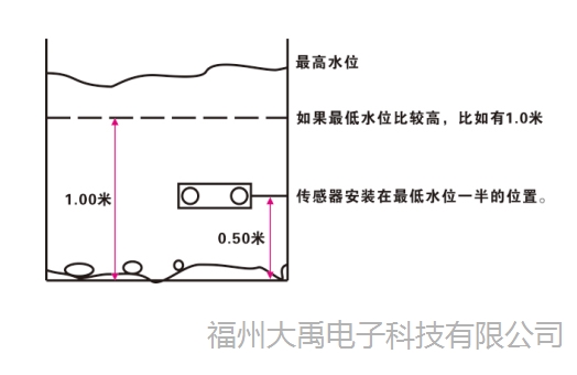
Figure 2.4.2 Sensor installed at half the depth of the lowest water level
2.5 Selection of Horizontal Installation Position
For channels with a width of less than 20 meters, if it is a rectangular channel, the sensor should be installed at 15–20% of the total channel width.
Why install at this position?
Because this position is closest to the average flow velocity across the entire horizontal section of the channel.
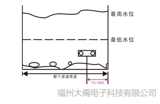
Figure 2.5.1 Sensor installed at 15–20% of the total channel width
For trapezoidal channels, the sensor should be installed at the junction between the slope and the bottom edge, also known as the "toe of the slope."
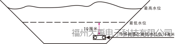
Figure 2.5.2 Sensor installed at the "toe of the slope" in a trapezoidal channel
The sensor must face directly into the direction of water flow, with left/right deviation not exceeding ±3°.
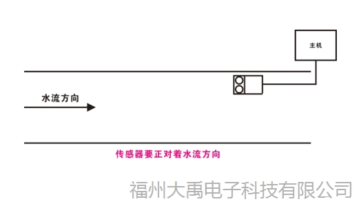
Figure 2.5.3 The sensor must face directly toward the direction of incoming water flow
The sensor must be parallel to the water surface.

Figure 2.5.4 The sensor must be parallel to the water surface
2.6 Sensor Installation in Circular Channels
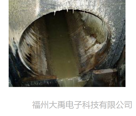
Figure 2.6.1 Circular pipe
In a circular pipe with sediment, install the sensor above the sediment level to prevent sediment from covering the sensor, which could affect measurement.
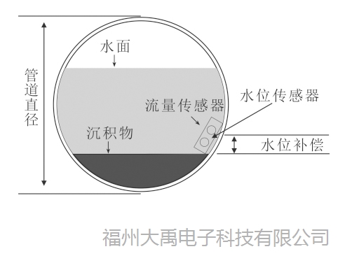
Figure 2.6.2 Installation position in a pipe with sediment
For installation in a pipe without sediment, the sensor can be installed directly on the pipe bottom. To prevent water flow from impacting and shifting the sensor's installation position, the sensor has a base at the bottom specifically designed for securing it to the pipe. The sensor should also be installed near the pipe outlet, which facilitates both installation and maintenance/replacement.
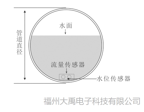
Figure 2.6.3 Installation position in a pipe without sediment
2.7 Sensor Installation in Rectangular Channels
For installation in a rectangular channel, if the water can be shut off to expose the channel bottom, a concrete platform can be constructed on the channel bottom with 4 bolts fixed onto it. The mounting base of the velocimeter can then be directly secured onto the bolts using nuts.
Advantage of this installation method: The sensor is less likely to be stolen.
Disadvantage: When maintenance is required, personnel must enter the channel to perform the work.
Figure 2.7.1 Installation in a rectangular channel at a reservoir outlet
For installation in a channel with sediment accumulation, the installation position should be raised to reduce the impact of sediment accumulation on measurement.
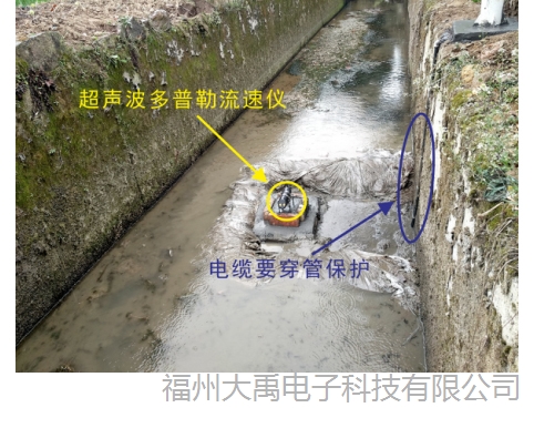
Figure 2.7.2 Installation in a rectangular agricultural irrigation channel — with sediment, silt, and aquatic weeds
For channels where water flow cannot be interrupted, the following side bracket mounting method can be used. When the sensor is covered by silt or large amounts of debris, simply loosen the screws connecting the entire bracket to the fixed bracket on the bank, and the sensor can be lifted out of the water for cleaning.
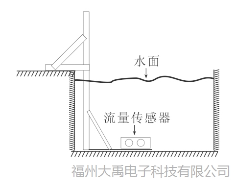
Fig. 2.7.3 Rectangular channel sensor bracket mounting method
A small measuring bridge can also be erected across the rectangular channel, with the flow velocity sensor fixed to the bridge via a bracket for measurement.
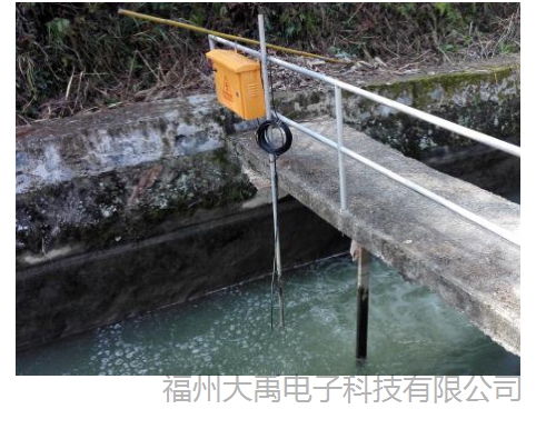
Fig. 2.7.4 Baiyun Reservoir in Yongtai County installed on a measuring bridge
2.8 Sensor installation in trapezoidal channels
If water flow can be interrupted, installation can be done as shown in Fig. 2.7.1. If water flow cannot be interrupted, a bracket is typically built on the bank, with two cantilevered rods extending downward from the bracket. The rods intersect at the sensor installation location, and the sensor is secured on the platform at the intersection point.
The two cantilevered rods are connected to the vertical pole via pivot joints, allowing vertical rotation. When needed, the sensor can be pulled out of the water for maintenance and servicing.
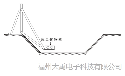
2.8.1 Schematic diagram of installation in trapezoidal channel - cantilever bracket
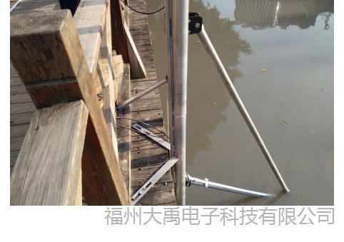
Fig. 2.8.2 Fuzhou urban river - cantilever bracket mounting method
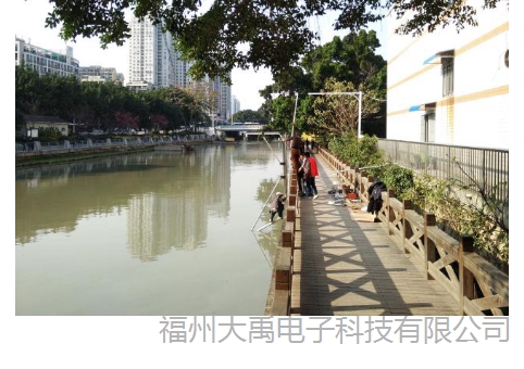
Fig. 2.8.3 Fuzhou urban river - cantilever bracket mounting method
If the slope is relatively long, the cantilever bracket mounting method may not be stable enough. The "rail-guided slide" mounting method can be adopted instead, where a railed slide is laid from the top of the trapezoidal channel to the bottom. The mobile platform is secured to the slide via guide rails and can move up and down. The sensor is fixed onto the slide.
This method is particularly convenient for routine inspection and maintenance.
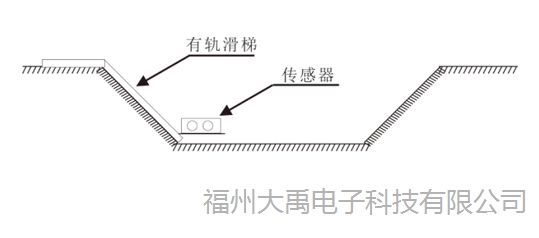
2.8.4 Schematic diagram of installation in trapezoidal channel - rail-guided slide
3. Product usage precautions
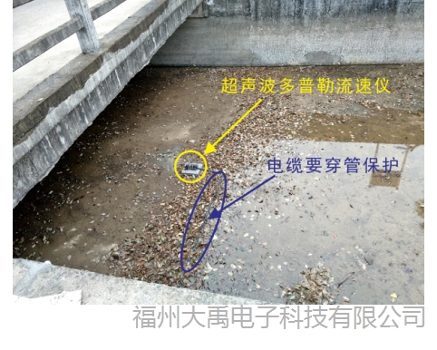
1. The cable connection between the sensor and other equipment should be routed along the bottom or inner wall of the channel and brought out of the water downstream from the sensor.
2. The cable must be protected by a conduit (PVC, PR, galvanized steel pipe, etc.). Direct water flow impact on the cable must be avoided. The conduit must be secured to the bracket or the channel wall.
3. The communication cable supplied with the sensor contains a vent tube inside; therefore, care must be taken not to bend it. After the communication cable is brought above the water surface, standard cable can be connected. At this point, the vent tube opening should face downward to prevent water and debris from entering or blocking the vent tube.
The cable connecting the sensor's 485 or 12VDC power supply must use shielded cable of at least 0.5 mm².
4. When using a wireless transmitter in irrigation channels, the antenna must be extended outside the instrument enclosure, and lightning protection measures must be implemented to prevent the antenna from becoming a lightning strike target.
5. Do not artificially pull or fling the cable, and do not strike the sensor housing.
6. Do not use the connecting cable as a load-bearing line to suspend heavy objects. The cable must be secured to the concrete wall of the channel and must not be allowed to sway.
7. Power supply can only be provided by battery or solar power. If 220VAC mains power is used, a linear power supply must be used to convert it to 12VDC. Switching power supplies must not be used.
8. For sites with flow velocity > 1.0 m/s, the mounting bracket strength must be reinforced to at least twice that of the standard bracket to ensure that strong currents will not wash away or damage the bracket.
FuzhouDayu Electronics——not onlyultrasonic Doppler velocity metermanufacturer, we are alsoultrasonic Doppler flow meterand river flow meter production experts, always adhering to the principle of providing customers with quality products and excellent service solutions.If you are interested in the above products or have any questions, please contact our online customer serviceQQ:2187169532, service hotline:0591-28082552. Fuzhou Dayu Electronics——Your dedicated purchasing consultant throughout the entire process!