
Principles and Applications of Ultrasonic Ranging Transducers
I. Principles and Classification of Ultrasonic Transducers
1. Definition of Ultrasonic Transducer: A device that converts signals or energy from other sources into the required ultrasonic signals or energy is called an ultrasonic transducer. There are many types of ultrasonic transducers. Electroacoustic transducers include piezoelectric transducers, magnetostrictive transducers, moving-coil transducers, electromagnetic transducers, and capacitive transducers. Hydrodynamic ultrasonic transducers include air-jet-driven whistles such as the vibrating rod whistle, vortex whistle, siren, circular plate whistle, and liquid-jet-driven reed whistles.
2. Ultrasonic Ranging Transducers: Ultrasonic ranging transducers are ultrasonic transducers capable of detecting distance in air. They must meet the following conditions:
First: High efficiency in transmitting and receiving sound waves in air.
Second: A certain degree of directionality.
Third: Short impulse response time, i.e., low Q factor and small blind zone. Ultrasonic ranging transducers are also called ultrasonic sensors or ultrasonic probes. They generally come in several types:
(1) Piezoelectric ceramic disc or Langevin transducer with matching layer structure
(2) Bending vibration type (parking sensor structure, buzzer disc structure)
(3) Longitudinal-bending vibration structure, using a longitudinal vibration transducer + bending vibration disc (high efficiency, complex process)
(4) Electrostatic transducers.
II. Directionality of Ultrasonic Transducers
Ultrasonic ranging transducers can be simply regarded as circular piston arrays.
The simplified formula for the -3dB opening angle of the main lobe of a circular piston transducer is:
Θ-3dB = 60° * (λ/D)
The accurate half-power angle formula is:
Θ-3dB = 2*arcsin(0.26*λ/a)
Sharpness angle: The angle between the first minima on either side of the main beam.
Θ = 2*arcsin(0.61*λ/a)
a = radius of the radiating surface
C is the speed of sound: C = 331.4 + 0.6*T
T is ambient temperature
f is frequency;
λ is wavelength: λ = C/f
D is diameter of the radiating surface
III. Transmitting and Receiving Response of Ultrasonic Transducers
1. Transmitting Response
Transmitting Voltage Response: In a sound field without interference effects, the ratio of the sound pressure at a specified point to the voltage applied across the transducer terminals is the transmitting voltage response.
Transmitting Current Response: In a sound field without interference effects, the ratio of the sound pressure at a specified point to the current flowing through the transducer is the transmitting current response.
Transmitting Power Response: In a sound field without interference effects, the ratio of the sound pressure at a specified point to the power applied to the transducer is the transmitting power response.
2. Receiving Voltage Sensitivity
The ratio of the open-circuit voltage at the output of the receiving transducer to the free-field sound pressure at the acoustic center position of the transducer that existed before the transducer was introduced into the sound field.
3. Relative Pulse-Echo Sensitivity
The transducer is excited by a signal with constant voltage and variable frequency. Ultrasonic pulses are transmitted from a standard plane reflector at a standard test distance z. The response characteristic of the first echo voltage from the transducer output versus frequency f is called the pulse-echo frequency response characteristic. Here, fp is the frequency of maximum pulse-echo response; the arithmetic mean (f1+f2)/2 of the two frequencies f1 and f2 where the pulse-echo response is half the maximum (-6dB) is called the pulse-echo center frequency fc. At the center frequency fc, the decibel value S of the ratio of the first echo voltage amplitude Ue to the excitation voltage UT of the transducer during measurement is called the relative pulse-echo sensitivity. S = 20*lg(Ue/UT). In practice, the relative pulse-echo sensitivity is relatively easy to set up on a test platform. Only a frequency-adjustable transmitting board, a reflector at a fixed distance, and an oscilloscope are needed.
IV. Transmit Drive for Ultrasonic Transducers
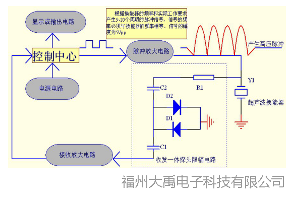
The transmit drive for ultrasonic transducers is relatively simple; the drive voltage can be anything as long as it does not exceed the rated voltage of the transducer. The rated voltage can be estimated as 200Vpp for a 1mm-thick ceramic disc. Of course, considering mechanical fatigue of the material, it is generally not recommended to drive with excessively high voltage. For a transducer, within the rated voltage range, the higher the voltage, the stronger the output sound pressure, and the farther the measurable distance. In practice, a stronger signal is not always better. A stronger signal also means stronger sidelobe signals and stronger reflections from nearby obstacles, which can easily interfere with signal processing equipment. Below are a system block diagram for ranging and a commonly used transmit circuit drawn by the author.
1. System block diagram of an ultrasonic ranging product.
2. Single-ended drive transmit circuit:
3. Push-pull drive transmit circuit.
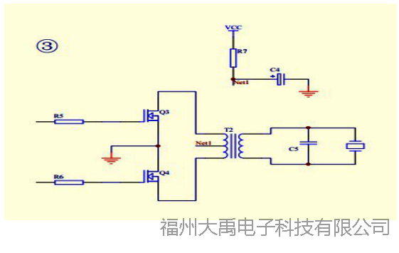
When transmitting ultrasonic waves, questions about matching often arise. Generally, matching involves two aspects: one is the matching between the transformer and the transducer; the other is adding an inductor to match the capacitance of the transducer.
The impedance of transducers is generally high, typically from a few hundred ohms to several kilohms. Therefore, matching the transformer output is relatively easy. Moreover, ranging transducers are pulse-driven, so the requirements for the transformer are not stringent. As for the transformer turns, the primary depends on the input voltage; typically, 1V corresponds to 0.8 turns. A turns ratio of 10 to 15 times is sufficient.
The transducer is a capacitive load. Without an inductor for matching, there will be some dielectric loss. However, since ranging transducers generally have a wide bandwidth, the author does not recommend using an inductor for matching; this way, your circuit can directly use transducers of different frequencies. If the product uses a single frequency and the transducer has a relatively high Q factor, an inductor can be added. The empirical formula for inductance is:
1.5*fo * 2 * 3.14 * sqrt(L*C) = 1
fo: operating frequency
sqrt: square root
L: series matching inductance
C: free capacitance of the transducer (can be measured directly with a multimeter)
V. Ultrasonic Signal Reception
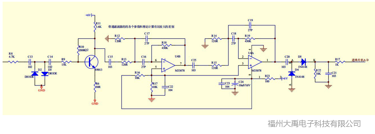
The receiving and amplifying circuit for ultrasonic ranging is essentially a small-signal amplification circuit. The received signal is relatively small, and if the product has a large measurement range, the dynamic range of the signal is large, from microvolts to several hundred millivolts. Generally, a high amplification factor is required. If the distance is long, the amplification circuit should preferably incorporate AGC or TGC processing. There are typically three processing methods.
The author commonly uses the following receiving and amplification circuits for ultrasonics.
1. Typical signal processing method one for ultrasonic ranging.
This signal processing method becomes measuring the time difference between two rising edges. It is relatively simple in software, but requires high stability of the hardware and high consistency of the transducers. Any electrical noise can cause false measurements. It also has high requirements for the environment. Reflections from nearby obstacles can easily become noise. No complex algorithms can be applied, so the product has poor adaptability to the environment.
2. Classic signal processing method two for ultrasonic ranging
This signal processing method converts the signal to its envelope, typically processed using AD sampling and threshold detection. It is more complex in software, and many algorithms can be applied; different algorithms result in significant differences in product adaptability. However, the stability requirements for hardware are lower, and environmental adaptability is stronger.
3. Classic signal processing method three for ultrasonic ranging
This signal processing method involves amplifying the raw signal, which can be sampled by AD and processed using correlation methods. It is more complex in software, and many algorithms can be applied; different algorithms result in significant differences in product adaptability. However, the stability requirements for hardware are the lowest, and environmental adaptability is also strong.
VI. Error Analysis of Ultrasonic Ranging
Whether in liquid or gas, the following factors affect the accuracy of ultrasonic ranging.
I. Factors affecting ultrasonic ranging accuracy in air:
1. Whether the medium is uniform and stable. In a stable propagation medium, the speed of sound is constant. Changes in the gas medium or its concentration will cause changes in sound speed, and these changes are difficult to compensate. For example, in a sealed tank containing volatile liquid.
2. Ambient temperature. When sound propagates in gas, a 1°C change in temperature causes a 0.6 m/s change in sound speed, a rate of about 0.17%. Therefore, if temperature measurement error is large or there is a temperature gradient, measurement errors will also be significant.
3. Pressure. The speed of sound changes with pressure: generally, higher pressure increases sound speed, and lower pressure decreases it. Pressure changes also affect the intensity of sound radiation and propagation attenuation, all of which can cause measurement errors.
II. Factors affecting ultrasonic ranging accuracy in liquid:
1. Medium: Whether the medium is uniform and stable. In a stable medium, sound speed is constant. Changes in the liquid medium or its concentration will cause changes in sound speed, and these changes are difficult to compensate. For example, in thick mud, from top to bottom, due to settling, the density of different layers varies significantly, causing noticeable changes in sound speed. At sea, variations in salinity across different areas also significantly affect sound speed.
2. Ambient temperature. When sound propagates in liquid, a 1°C change in temperature causes a 1 m/s change in sound speed, a rate of about 0.06%. Therefore, if temperature measurement error is large or there is a temperature gradient, measurement errors will also be significant. In water, due to sunlight and water currents, different temperature layers can easily form. In deep natural waters, ultrasonic measurement errors are typically 1% to 2%.
3. Pressure. The speed of sound changes with pressure: generally, higher pressure increases sound speed, and lower pressure decreases it. Pressure changes also affect sound radiation intensity and propagation attenuation, which can cause measurement errors. However, compared to air, the effect of pressure in liquids is smaller.
VII: Summary
Ultrasonic ranging is not a very complex technology, but doing it well is not easy. It requires analyzing the operating environment, selecting the appropriate ultrasonic transducer, choosing suitable transmit/receive circuits and software processing methods, and applying appropriate environmental compensation factors to truly make a good product.