
Dayu Electronic Anemometer Transducer: How Large Is the Instantaneous Emission Current? Selection Advice in One Go
Ultrasonic transducers are driven by pulsed voltage, and there is a transient current surge at the moment of emission. How large this surge current actually is directly affects the design of the driving circuit and component selection, making it an unavoidable issue for many engineers developing roadway anemometers.
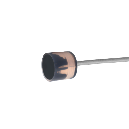
Taking DYA-40-12CA as an example, the instantaneous emission current is approximately 3–5 A. However, this value is not fixed—it depends on the combined effects of the emission voltage, transducer impedance, and the overall circuit loop impedance. Higher voltage results in higher current, and higher impedance results in lower current. Therefore, it is a dynamically changing value rather than a precise, constant point.
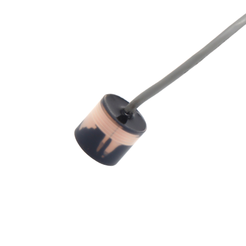
Next is the key point: when selecting components, do not base your choice strictly on the transient value of 3–5 A. The pulse emission current comes and goes quickly, representing a typical transient high-current surge, whereas most component datasheets specify current ratings under continuous operating conditions. If the design margin is insufficient, the driving transistors and power supply chips can easily overheat or even burn out under repeated surges.
Therefore, our recommendation is clear: select components with a margin for 10 A of current:
First, leave margin. 3–5 A is a typical value, but under actual operating conditions, if the emission voltage fluctuates or individual transducer differences lead to lower impedance, the instantaneous current can surge even higher. Choosing a 10 A rating gives you more than double the safety cushion.
Second, withstand surges. Underground roadway environments have large temperature differences and high humidity. Components such as MOSFETs and freewheeling diodes will see increased on-resistance after long-term aging, making transient stress more severe. Insufficient margin can lead to problems after batch installation.
Third, facilitate debugging. During the R&D phase, you may also try higher emission voltages to improve sensitivity. A 10 A foundation allows you to adjust without repeatedly changing components.
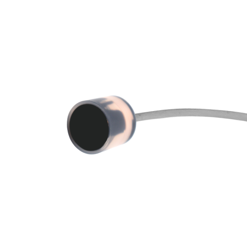
The goal is to ensure that every part of the driving circuit can withstand current spikes, especially in environments like coal mine roadways where equipment reliability is paramount. Leaving extra margin during selection can save a lot of trouble in the field.
If you are currently designing an emission board and have questions about driving topologies or protection circuits, feel free to reach out to the Dayu Electronics technical team.