
Dayu Electronics Ultrasonic Level Difference Meter Installation Guidance Case at a Wastewater Treatment Plant in Sichuan
In municipal wastewater treatment systems, the screen chamber is the first line of defense for intercepting suspended solids and protecting pumps and downstream treatment units. To ensure that the screen machine operates automatically and efficiently based on the water level difference between the front and back, enabling precise removal of screenings, stable and reliable level measurement is crucial.
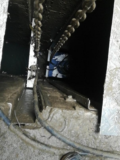
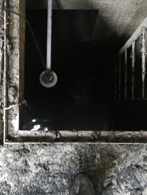
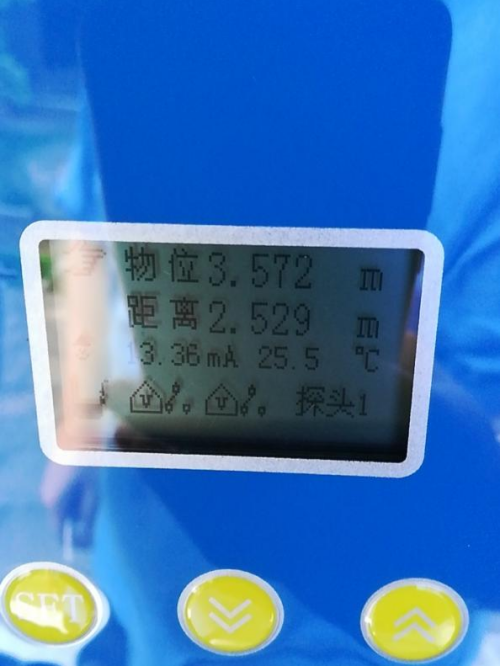
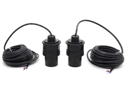
Recently, the Dayu Electronics technical team visited a large wastewater treatment plant in Sichuan and successfully completed on-site installation guidance and commissioning of the ultrasonic level difference meter, effectively resolving the challenge of balanced level measurement before and after the screen, providing a solid guarantee for the intelligent operation of the plant.
1. Applicable Working Conditions
? Suitable scenarios:
Media: Surfaces of liquids such as water, wastewater, acid/alkali solutions, and oils (must form an effective acoustic reflection surface).
Environment: Open vessels, open channels, drainage pumping stations, and before/after trash racks.
Measurement range: Typically 0.3 to 15 m (the larger the range, the larger the blind zone).
? Situations that are strictly prohibited or highly unsuitable (will directly cause measurement failure):
Heavy foam: Foam absorbs sound wave energy rather than reflecting it (e.g., biological aeration tanks, paper mill white water), causing readings to fluctuate or drop.
Strong steam/water mist: Sound velocity varies drastically in steam, and water mist attenuates the signal (e.g., high-temperature dyeing machines, steam-traced tanks).
Dust/particulates: Sound waves are scattered by dust (e.g., cement silos, coal powder silos).
Violent liquid surface fluctuations/vortices: The reflection surface tilts, and the echo deviates from the transducer (requires a stilling well or guide pipe).
Rapid temperature changes of the medium: Changes exceeding ±5°C/min cause lag in sound velocity compensation, leading to additional errors.
2. Key Precautions (Maintenance Pitfall Guide)
Temperature compensation: Although the instrument comes with a built-in temperature sensor, if the sensor is exposed to direct sunlight or installed above a heat source, the measured temperature will not match the actual temperature along the sound path, causing systematic errors. It is recommended to provide shading and insulation for the sensor.
Blind zone: The “maximum level” displayed by the instrument must never enter the blind zone (typically 0.3 to 0.5 m from the transducer face). If it does, the instrument will output an erroneous current or retain the last value.
Interfering echoes: Crossbeams, stiffeners, and ladders inside the vessel can produce false echoes. On-site, use a HART handheld communicator or software to perform “echo curve suppression” (i.e., the learning function) to mask fixed obstacles.
Condensation and fouling: If water droplets or sludge accumulate on the transducer face, acoustic coupling efficiency drops significantly. In winter, prevent icing; in summer, prevent condensed water droplets from obstructing the transducer (a drip-proof shield can be installed during installation).
Wiring requirements: For two-wire loop-powered systems, calculate the cable voltage drop (ensure terminal voltage ≥ 17 VDC). For four-wire systems, avoid running the cable in the same conduit as VFD power cables, as electromagnetic interference can cause erratic readings.
3. Mandatory Installation Requirements (Directly Affect Accuracy)
Installation accounts for more than 70% of on-site failure causes. Please pay special attention to these four points:
Verticality: The transducer face must be installed horizontally, at 90° perpendicular to the liquid surface. Even a 2° tilt will attenuate the echo strength by more than 50%.
Avoid obstacles: The sound beam emitted by the transducer is conical (half-angle approximately 7° to 15°). When installing, maintain a horizontal distance of ≥ 0.5 m from the vessel wall or obstacles, and ensure there are no protruding objects within the cone angle (calculated as: obstacle height = distance × tan15°).
Installation position: Never install directly above the inlet (where the liquid surface is disturbed) or directly above the pump suction (where vortices occur). The ideal position is at one-third to one-half of the vessel diameter, away from vigorous agitators.
Cable installation (remote type): The coaxial cable length between the transducer and the transmitter is strictly limited (typically recommended ≤ 50 m, and must use a dedicated low-capacitance cable). If longer, a lightning/signal amplifier must be added; do not arbitrarily extend or cut standard shielded cable.
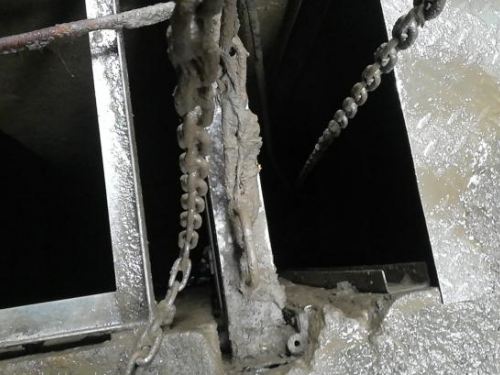
Special Reminder
If you are measuring open-channel flow, the upstream-downstream level difference is usually very small (e.g., a few centimeters), and absolute errors are magnified. It is strongly recommended:
Do not calculate the difference using two separate single-channel instruments; instead, use an integrated dual-channel level difference meter, which samples synchronously to eliminate time differences in surface fluctuations. Additionally, a stilling well must be installed (so the transducer measures a quiescent water surface); otherwise, integrated flow errors can exceed ±5%.
The successful implementation of this case once again confirms Dayu Electronics' technical expertise and engineering practice capability in the field of ultrasonic level measurement. Whether in complex industrial sites or demanding municipal conditions, Dayu Electronics provides one-stop solutions from product selection and installation guidance to after-sales support. We are committed to empowering the digital transformation of the environmental and water treatment industry with precise sensing technology!