
Dayu Electronics: The "Invisible Trap" in Phased Array Imaging: How Element Spacing Determines Grating Lobe Size
In phased array ultrasonic testing, people often focus on parameters like element count, frequency, and bandwidth. But there is another equally critical indicator that is easy to overlook yet directly determines whether the image is "clean"—it is the element spacing, also known as pitch.
Element spacing does not directly affect resolution or penetration depth, but it quietly causes trouble: it creates artifacts. The most typical and troublesome of these is the grating lobe.
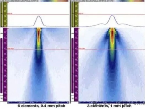
What is a grating lobe? Simply put, it is a "beam going in the wrong direction."
Normally, a phased array probe controls the transmit delays of each element so that sound waves superimpose to form a main beam pointing in the direction of interest. However, if the element spacing is too large, in addition to the main beam, the system will also "unintentionally" emit one or even multiple high-energy beams—pointing at completely wrong angles. These extra beams are called grating lobes.
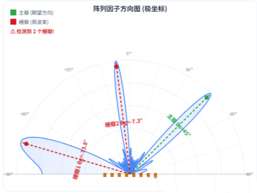
You can imagine it this way: you only want to shine a spotlight straight ahead, but because the lamp beads are spaced too far apart, two strong beams also emerge from the sides. That is not "precision illumination" but "scattering light everywhere."
Consequences of grating lobes: false defects, real interference
The energy emitted by grating lobes propagates normally inside the workpiece and reflects back after encountering structures, boundaries, or defects. The receiver cannot distinguish whether the echo comes from the main beam or a grating lobe, so it displays a nonexistent "reflector" at a wrong position on the screen. The results are:
- False defects: bright spots appear in multiple places even when there are no cracks.
- Masking real defects: grating lobe echoes overlap with genuine defect signals, leading to missed detection or misjudgment.
- Severe degradation of image signal-to-noise ratio, making the entire image cluttered and unreliable.
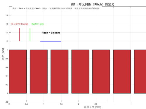
How element spacing determines the "size" of grating lobes
According to the basic principles of ultrasonic phased arrays, element spacing must satisfy a constraint: it must not exceed half the wavelength. This condition comes from the mathematical criterion for avoiding grating lobes—you don't need to delve into the derivation, but the conclusion is clear: when element spacing exceeds half a wavelength, grating lobes begin to appear; the larger the spacing, the stronger the grating lobe amplitude, the more they deviate from the main beam, and the more severe the image contamination. Conversely, when spacing is kept at or below half a wavelength, grating lobes can be suppressed to negligible levels.
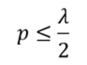
Therefore, when designing phased array probes, companies calculate the maximum allowable element spacing based on the wavelength corresponding to the highest operating frequency. For example, a 5MHz probe in steel has a wavelength of about 1.18mm, and half a wavelength is about 0.59mm. If the element spacing exceeds 0.6mm, the risk of grating lobes increases significantly. This is also why high-frequency, high-resolution phased array probes often have denser element spacing and higher manufacturing difficulty.
Dayu Electronics' recommendation
If you encounter strange "artifacts" in images when using phased array equipment, or if there are extra echoes from a known reflector on a standard test block, it is worth suspecting grating lobes. As a system integrator or end user, the most important thing to do is: when selecting a phased array probe, confirm with the supplier that the element spacing meets the requirement of not exceeding half a wavelength. This is the most effective way to avoid grating lobe interference at the source.
In the design of phased array transducers, Dayu Electronics strictly controls the matching relationship between element spacing and frequency, and through dual verification of simulation and actual testing, ensures a clean main beam and controllable artifacts. We don't just sell probes—we help you "filter out" the light that shouldn't be there.