
Dayu Electronics: Troubleshooting Guide for Ultrasonic Distance Sensor Drive and Reception Faults
Some customers have reported that during the use and commissioning of ultrasonic distance sensors, they occasionally encounter faults such as abnormal squealing from the transformer and probe, and a fixed echo signal amplitude (e.g., constant at 1V) that does not vary with distance. These issues not only affect measurement accuracy but may also point to fundamental defects in circuit design or operating mode. In response to such phenomena, Dayu Electronics, drawing on extensive technical experience, has organized a systematic troubleshooting approach to help quickly identify the root cause and ensure stable sensor operation.
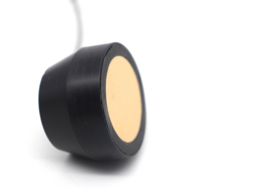
Step 1: Verify drive signal quality
Abnormal squealing is often directly related to the drive signal. First, use an oscilloscope to directly measure the drive voltage signal across the transducer. A normal drive pulse should have a clean waveform, sufficient amplitude, and sharp edges. For example, in a typical high-voltage drive scheme, the peak-to-peak voltage (Vpp) may approach several hundred volts. If the drive signal waveform is distorted, has insufficient amplitude, or contains abnormal oscillations, it may force the transformer core or the transducer's piezoelectric element to operate away from resonance, generating audible mechanical noise (squealing). This step is crucial to confirm whether the 'source' is healthy.
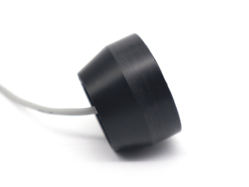
Step 2: Isolate and test the receive circuit
When the echo signal amplitude remains fixed, the problem may not lie in the acoustic propagation path but in the receive circuit itself. To accurately diagnose, it is recommended to temporarily disconnect the drive connection to the transducer and use an external signal generator to simulate the echo signal. Inject a small-amplitude sine wave (with frequency matching the transducer's center frequency) directly into the input of the receive circuit. Then monitor the final output signal of the receive circuit. If the output amplitude varies linearly with the input signal, it proves that the receive amplification, filtering, detection, and other stages are basically normal. If the output remains fixed, the problem is clearly in the receive circuit, and you should focus on checking its gain settings, whether it has entered saturation, or if there is component failure.
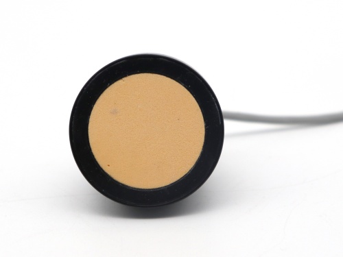
Step 3: Confirm the drive operating mode
Ultrasonic distance measurement is definitely not a continuous wave mode. A properly designed system should follow a 'transmit-wait-receive' pulse cycle. Under normal conditions, the transmit circuit drives the transducer for a very short period (corresponding to 15-25 pulses) and then immediately turns off, entering a long quiet receive window (several hundred milliseconds) to 'listen' and analyze the weak echo signal. After processing, the next transmit cycle begins. If the drive signal becomes continuous or the interval is extremely short, the system will always be masked by its own strong transmission signal, making it impossible to distinguish the real echo, and the output signal will lock to a fixed value (such as 1V). This is usually caused by software timing or hardware enable logic errors.
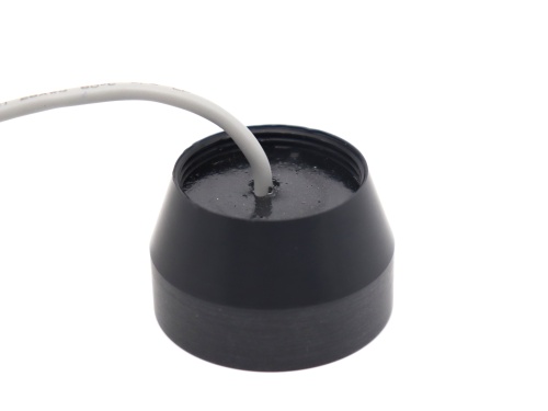
Through the above three steps of systematic troubleshooting from the outside to the inside and from transmission to reception, most drive- and signal-related faults can be accurately identified. Dayu Electronics not only provides high-performance ultrasonic transducers and probes but also offers solid technical support for your system integration, helping you build stable and accurate distance measurement solutions.