
Dayu Electronics: Protection and Optimization of Ultrasonic Depth Sounder Receiver Circuits
In the design and use of an ultrasonic depth sounder, a professional and common question arises: if a protection resistor is connected in series with the receiver circuit of a 250kHz transducer to absorb and attenuate the high-voltage pulses from the transmitter circuit, will this inevitably lead to excessive weakening of the received echo signal, thereby affecting final measurement accuracy? Dayu Electronics' technical practice provides a clear and dialectical answer: yes, any measure intended to protect the receiver circuit will objectively introduce signal attenuation; however, this 'controlled weakening' is an absolute prerequisite for ensuring long-term reliable operation of the equipment, and excellent design lies in finding the optimal balance between protection and sensitivity.
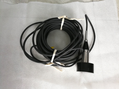
The working principle of an ultrasonic depth sounder is essentially a 'question and answer' of sound waves: the transmitter circuit momentarily drives the transducer to produce a high-intensity ultrasonic pulse, and then the same transducer quickly switches to receiving mode to capture the weak echo returning from the water bottom. The core contradiction here is that the driving voltage at the moment of transmission is extremely high (up to hundreds of volts), while the signal that the receiver circuit needs to detect is extremely weak (often at the millivolt level). If effective electrical isolation is not performed between the two, the huge transmit voltage will surge directly into the delicate receiver circuit amplifier at the moment of switching, which is equivalent to an 'electrical tsunami' that will directly cause the components in the receiving channel to overload and burn out, permanently damaging the equipment.
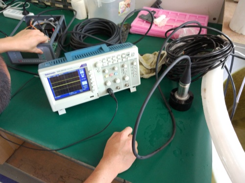
Therefore, inserting protective components such as resistors and capacitors in the receiving loop constitutes a 'buffer isolation zone.' Its primary and fundamental purpose is survival. They act like an intelligent damper and filter, effectively absorbing and attenuating the destructive high-voltage pulse energy, ensuring that only safe signal levels enter the subsequent processing chip. This is the cornerstone of all high-reliability ultrasonic measurement equipment design. Objectively speaking, this barrier, while blocking hazards, inevitably causes a certain degree of attenuation to all passing signals, including the effective echoes we need.
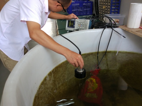
However, this absolutely does not mean that measurement performance must be compromised. Dayu Electronics believes that true professional design is not simply 'inserting a resistor in series' but a systematic project of balancing and compensation. Our engineers need to:
1. Precisely calculate the insertion loss caused by the protection network through simulation and actual measurement, and select components with stable temperature characteristics and extremely low noise to keep unavoidable attenuation within the smallest and most predictable range.
2. Perform precise gain compensation in the subsequent amplifier chain and focus on optimizing the noise performance of the preamplifier to ensure that, after protection is introduced, the system can still clearly extract effective echo signals that are far above background noise.
3. Use modern digital signal processing techniques to filter, identify, and enhance the echo after it has been 'shaped' by the protection circuit, further improving the signal-to-noise ratio.
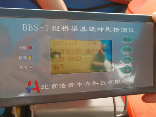
In short, sacrificing a small amount of signal strength to ensure circuit safety is a necessary cost; and minimizing this cost through meticulous system design while ensuring that the final signal-to-noise ratio meets the requirements for precise depth measurement is precisely a manifestation of Dayu Electronics' core technical capabilities. In every ultrasonic depth sounder we deliver, this dynamic and precise balance is achieved internally, ensuring stable and accurate depth measurement with absolute safety, whether in a calm lake or in complex hydrological environments.