
Dayu Electronics: The Key Principle of "Vibration Isolation" in Gas Flow Meter Transducer Installation
During the installation and commissioning of ultrasonic gas flow meter transducers, ensuring the proper operation of the transducer—the core sensing element—is fundamental to measurement accuracy. Technicians frequently encounter various questions regarding transducer installation. One typical question is: when two metal-housed transducers are separately connected to a metal measuring pipe, will an electrical path formed between them affect the signal? Is insulation from the pipe required?
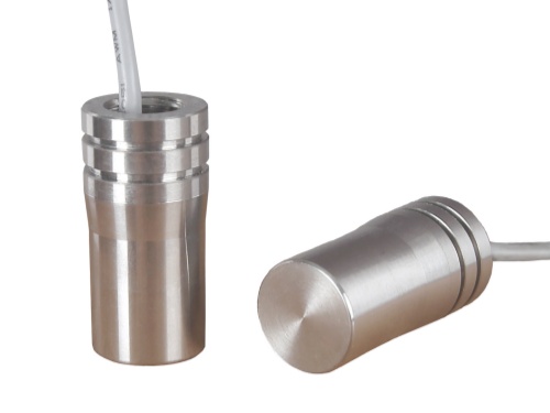
In response to this common concern, Dayu Electronics provides a clear analysis and solution from a professional perspective. First, regarding the need for electrical insulation, it is not absolute and primarily depends on the electrical environment of the pipe at the installation site. If the pipe itself carries a potential difference due to on-site conditions (such as static electricity, stray currents, etc.), insulation treatment is necessary to prevent interference or ensure safety. Conversely, under normal operating conditions—if the pipe housing is not electrically live and the internal circuitry of the flow meter has properly handled the ground (GND) loops of both transducers—additional measures solely for "insulation" purposes are typically unnecessary. In many transducers, the ground wire design may naturally be connected to the housing, which is normal.
However, this raises a more universal and subtle key technical point: mechanical vibration isolation. When both the transducer housing and the metal pipe are made of rigid metal materials, one critical physical phenomenon must be given high priority—vibration conduction.
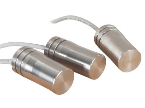
The operating principle of ultrasonic gas flow meter transducers relies on the transducer transmitting and receiving air-coupled ultrasonic signals through the gas flow, with flow velocity determined by calculating the time difference. When the transmitting transducer operates, its piezoelectric crystal generates high-frequency mechanical vibrations. In addition to propagating through the gas as acoustic waves—the primary path—part of this vibration energy is also coupled directly from the metal housing to the metal pipe wall, where it propagates rapidly along the pipe wall as solid-borne sound waves and is picked up directly by the receiving transducer through its housing.
This "pipe-wall sound transmission," or "mechanical crosstalk," is a direct propagation path that bypasses the measured gas. It causes the receiving circuit to pick up interference signals prematurely, potentially leading to incorrect determination of ultrasonic time-of-flight, and ultimately resulting in severe measurement errors or even complete failure of the flow reading. The essence of this problem is a "short circuit" of vibration energy, not an electrical issue.
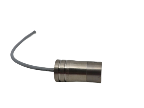
Therefore, when connecting metal transducers to a metal pipe, a critical installation step is required: O-ring rubber seals, dedicated flat washers, or other elastic vibration-isolating materials must be used to effectively isolate the transducer mounting surface from the pipe wall. The core purpose of this measure is precisely to cut off the direct path of vibration conduction through solid structures, ensuring that the receiver only detects the valid ultrasonic signal that carries flow velocity information and propagates through the gas medium. In short, this is for "vibration isolation"—not primarily for "electrical insulation."
Dayu Electronics has always emphasized that correct installation is a key factor in bringing out product performance. We not only provide high-performance, high-reliability transducers for gas flow meters, but also are committed to offering customers comprehensive technical guidance. Understanding the key principle of "vibration isolation" will effectively help avoid installation errors and ensure that your flow measurement system achieves the most accurate and stable data foundation.