
In-Depth Analysis of the Precise Correspondence Between Transducer Drive Coil Turns Ratio and Frequency
When designing and applying ultrasonic transducers, in addition to the transducer's own performance, the design of its drive circuit is equally critical. Recently, a professional question regarding the core component of drive circuits was raised: “What configurations are commonly used for the turns ratio between the primary and secondary coils of the transformer that drives the transducer?”
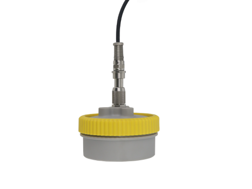
This question touches upon the circuit foundation for efficient and stable operation of ultrasonic systems. The answer is specific and insightful: Typically, based on the core operating frequency of the transducer, two mainstream turns ratio configurations are matched. For example, a 5:15 ratio is commonly used to drive higher-frequency transducers operating above 200 kHz, while a 16:270 ratio is designed for low-to-mid frequency transducers operating above 10 kHz but below 200 kHz. These are not arbitrary numbers; they are based on comprehensive considerations of electromagnetics, acoustic matching, and engineering efficiency.
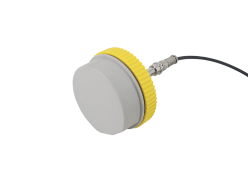
Why does the “turns ratio recipe” of the drive transformer need to change with frequency? The drive transformer is responsible for impedance transformation and energy transfer. The turns ratio must be adjusted according to the transducer frequency, primarily for three reasons:
1. Matching impedance characteristics: The equivalent impedance of the transducer varies with frequency; an appropriate turns ratio achieves impedance matching and maximum power transfer, avoiding energy loss.
2. Optimizing drive voltage and current: High- and low-frequency transducers require different electrical parameters. Adjusting the voltage via the turns ratio both excites the piezoelectric ceramic effectively and prevents breakdown or overheating.
3. Adapting circuit topologies: Different frequencies correspond to different power components and circuit designs. The turns ratio must be coordinated to control losses, temperature rise, and interference, ensuring stable operation.

Therefore, when you ask “how many turns ratios exist,” the essence is to find out how to match a “tailor-made” drive energy for a transducer at a specific frequency. The 5:15 and 16:270 ratios are just two typical examples; behind them lies a rigorous “frequency-impedance-power” matching design system. Dayu Electronics not only provides high-quality transducers but also offers matching drive solutions or core components based on the customer's application frequency and power requirements, ensuring that every conversion from electrical energy to acoustic energy is precise, efficient, and reliable.