
An Overview of Ultrasonic Flowmeters and Doppler Current Meters
Ultrasonic flowmeters have only come into application over the past decade or so with the rapid development of integrated circuit technology. Depending on the detection method, they can be classified into different types, including transit time difference, Doppler, beam deflection, noise, and correlation methods.
An ultrasonic flowmeter consists of three main parts: ultrasonic transducers, electronic circuitry, and a flow display and totalization system. The transmitting ultrasonic transducer converts electrical energy into ultrasonic energy, which is emitted into the fluid being measured. The receiver captures the ultrasonic signal, which is then amplified by the electronic circuitry and converted into an electrical signal representative of the flow rate, which is supplied to the display and totalizer for indication and integration. In this way, flow detection and display are achieved.
Ultrasonic Doppler current meters operate on the principle of the Doppler effect from physics. According to the acoustic Doppler effect, when there is relative motion between the sound source and the observer, the observed sound frequency differs from the frequency emitted by the source. This frequency change caused by relative motion is proportional to the relative velocity between the two objects. An ultrasonic Doppler current meter is a device used to measure water flow velocity in pipes, channels, or rivers. It is mainly applied in the following areas: · Flood disaster monitoring · Sewage discharge · Natural streams and rivers · Municipal water supply and drainage · Water loss/infiltration monitoring · Irrigation flow monitoring · Estuary and tidal studies · Fisheries/water conservancy · Coastal erosion studies · Culvert flow monitoring · Road drainage monitoring · Canal flow studies · River flow monitoring.
The main disadvantages of ultrasonic flowmeters at present are that the measurable fluid temperature range is limited by the temperature resistance of the ultrasonic transducer (aluminum) and the coupling material between the transducer and the pipe, and also by the incomplete original data on the speed of sound in the fluid at high temperatures. Currently, in China, they can only measure fluids below 200°C. In addition, the measurement circuitry of an ultrasonic flowmeter is more complex than that of a general flowmeter. This is because in general industrial metering, liquid velocities are often several meters per second, while the speed of sound in the liquid is about 1500 m/s. The change in the speed of sound caused by the variation in the measured fluid velocity (flow rate) is at most on the order of 10⁻³. If the required accuracy for flow velocity measurement is 1%, then the accuracy for measuring the speed of sound must be on the order of 10⁻⁵ to 10⁻⁶. Therefore, sophisticated measurement circuitry is essential, which is exactly why ultrasonic flowmeters could only find practical application after the rapid development of integrated circuit technology.
Ultrasonic flowmeters commonly use piezoelectric transducers. They utilize the piezoelectric effect of piezoelectric materials, using an appropriate transmitting circuit to apply electrical energy to the piezoelectric element of the transmitting transducer, causing it to generate ultrasonic vibrations. The ultrasonic wave propagates into the fluid at a certain angle, and is then received by the receiving transducer, where it is converted back into electrical energy by the piezoelectric element for detection. The transmitting transducer operates on the inverse piezoelectric effect, while the receiving transducer utilizes the direct piezoelectric effect.
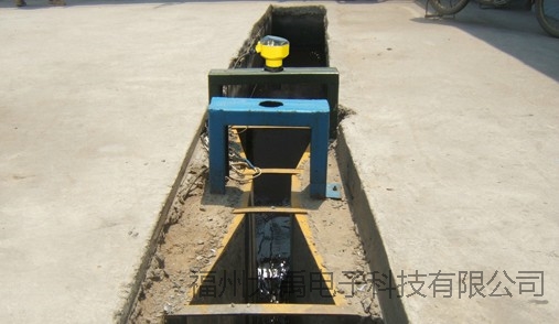
Ultrasonic flowmeter in the field
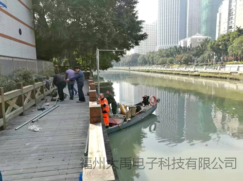
Doppler current meter installation site
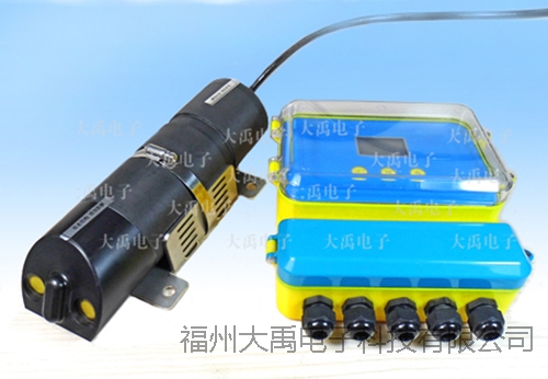
Actual product image of the ultrasonic Doppler current meter
For more information, please visit our website or call us at: 0591-28082552