
Dayu Electronics Ship Lock Upstream and Downstream Measurement Solution for Vessel Draft Depth
Ship Lock Upstream and Downstream Measurement
Vessel Draft Depth Measurement Solution
1. Site Conditions
1.1 The overall navigation channel environment is shown below.
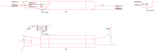
1.2 Specific data
Upstream measurement location, width50.967 m;
Upstream maximum navigable water level100.0 m
Upstream minimum navigable water level85.0 m
Upstream approach channel bottom elevation81.7 m
Downstream measurement location, width56.675 m;
Downstream maximum navigable water level79.10 m
Downstream minimum navigable water level69.00 m
Downstream approach channel bottom elevation64.20 m
1.3Other conditions
Site annual minimum temperature: provided by user;
Site annual maximum temperature: provided by user;
Site maximum flow velocity: provided by user;
Site minimum flow velocity: provided by user;
2. Solution
2.1 Upstream channel
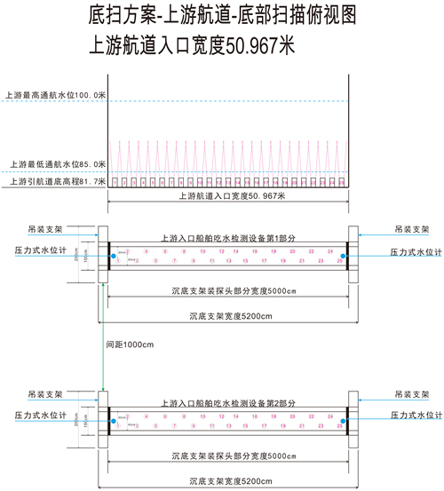
The upstream channel entrance width is50.967 m. A cross-shaped support frame is installed at the bottom with a total width of52.000 m. Each side has1 m of fixed bracket secured by slings, and the middle50.000 m is the load-bearing bracket for installing ultrasonic underwater ranging sensors.
On the load-bearing bracket, an ultrasonic underwater ranging sensor is installed every2 m, for a total of25 sensors. They transmit vertically toward the water surface to measure the distance to the ship's bottom.
Refer to the schematic diagram for the actual dimensions of the lifting bracket and load-bearing bracket.
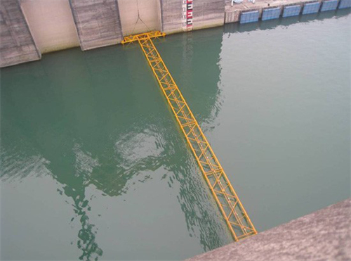
One pressure-type water level meter is placed on each side of the load-bearing bracket to measure the water level above the bracket.
One sludge concentration meter is placed on each side of the load-bearing bracket to measure the sludge content in the water near the bracket. If the sludge content exceeds a certain threshold, the bracket must be raised to avoid the sludge accumulation.
Each end of the entire bracket has2 attachment points for slings, allowing the bracket height to be adjusted by the hoist at the top of the ship lock. During normal operation, the bracket is placed on the bottom of the ship lock. If silt accumulates at the bottom, the installation position must be raised to avoid the silt settling layer.
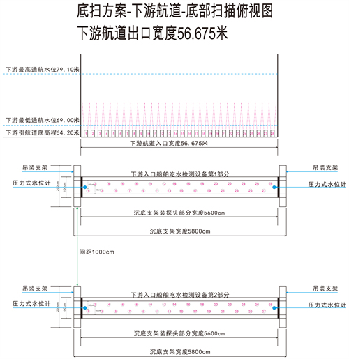
2.2 Downstream channel
The downstream channel entrance width is56.675 m. A cross-shaped support frame is installed at the bottom with a total width of58.000 m. Each side has1 m of fixed bracket secured by slings, and the middle56.000 m is the load-bearing bracket for installing ultrasonic underwater ranging sensors.
On the load-bearing bracket, an ultrasonic underwater ranging sensor is installed every2 m, for a total of28 sensors. They transmit vertically toward the water surface to measure the distance to the ship's bottom.
Refer to the schematic diagram for the actual dimensions of the lifting bracket and load-bearing bracket.
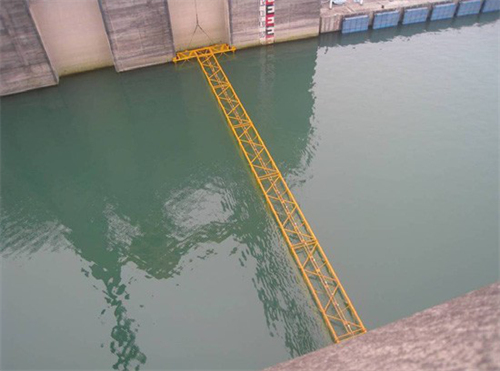
One pressure-type water level meter is placed on each side of the load-bearing bracket to measure the water level above the bracket.
One sludge concentration meter is placed on each side of the load-bearing bracket to measure the sludge content in the water near the bracket. If the sludge content exceeds a certain threshold, the bracket must be raised to avoid the sludge accumulation.
Each end of the entire bracket has2 attachment points for slings, allowing the bracket height to be adjusted by the hoist at the top of the ship lock. During normal operation, the bracket is placed on the bottom of the ship lock. If silt accumulates at the bottom, the installation position must be raised to avoid the silt settling layer.
2.3 Shore-based equipment
All underwater equipment is centralized in2 control cabinets. All measurement data is transmitted to the industrial PC, which collects and stores the data and outputs results based on the measurements:
① The draft depth of each vessel passing through.
② The minimum draft depth can be manually set.
③ If the draft depth exceeds the minimum threshold, a switch signal is output to other equipment, and an alarm is displayed on the industrial PC.
④ An alarm is triggered if the sludge content in the water at the bracket exceeds the standard, outputting a relay signal and displaying an alarm on the industrial PC.
⑤ All measured data can be stored on the industrial PC for365 days.
3. Other requirements
3.1 The on-site power supply must be AC180VAC to250VAC and equipped with a voltage stabilizer to prevent voltage fluctuations that could cause measurement errors or failure.
3.2 Within 20 m of the shore-based equipment installation location, there must be no interference sources such as frequency converters, electric motors, or water pumps larger than 5KW.
3.2 Shore-based equipment must be installed indoors or under a sufficiently sturdy rain shelter to ensure that no amount of rain can reach the equipment.
3.3 Direct sunlight must not shine on the equipment.
3.4All cables outside the equipment must be protected by galvanized steel conduit to prevent crushing, rolling, abrasion, or impact by personnel or equipment.
3.5 No corrosive gases or liquids may be present around the shore-based equipment and cables.
3.6 Operating environment temperature: -10 to +50°C; operating environment pressure: one standard atmosphere; operating environment humidity: ≤90%RH non-condensing.
3.7 The cable length from the farthest sensor to the shore-based equipment must not exceed 100 m.