
Installation Position and Layout Logic of Rail Inspection Transducers [Dayu Electronics]
The installation position of rail inspection transducers directly determines the defect detection rate and inspection accuracy. It must be precisely set based on the structural characteristics of the rail, the inspection method, and the distribution patterns of defects. The core installation positions and layout logic are as follows:
The rail head area is one of the key installation zones for transducers, mainly targeting defects on the rail head tread, both sides, and internal defects. On the rail head tread, straight-beam transducers are typically installed vertically to directly detect defects such as delamination and porosity beneath the tread. Angle-beam transducers are symmetrically arranged on both sides along the width of the rail head, with refraction angles mostly ranging from 65° to 75°, utilizing ultrasonic reflection characteristics to cover internal cracks and transition zone cracks in the rail head. Such installations must ensure that the transducers are in close contact with the rail head surface. In some scenarios, accessory-free detachable fixing methods are adopted to balance inspection efficiency and equipment versatility.
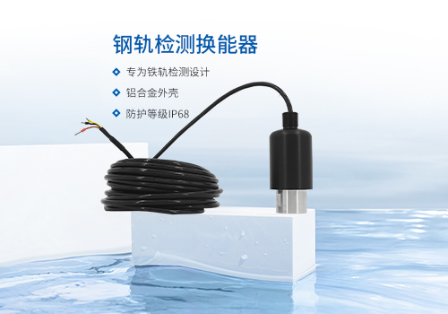
The rail web area is the main concentrated installation zone for transducers, suitable for detecting defects such as transverse cracks and inclusions in the rail web. Angle-beam transducers are symmetrically installed on both sides along the width of the rail web, with refraction angles generally ranging from 37° to 45°, allowing the beam to penetrate obliquely through the rail web body and the connection areas with the rail head and rail base. Some inspection devices add a straight-beam transducer at the center of the rail web to supplement detection of defects in the central region. During installation, coupling is achieved through 1-3mm silicone or tin foil to ensure efficient acoustic energy transmission while avoiding positional conflicts with rail fasteners.
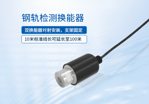
The installation of transducers in the rail base area must be arranged according to a zoning principle to address defect variations in different areas of the rail base. Based on the energy concentration characteristics of the sound field, the rail base is divided into the short leg side area, the area below the rail web, and the middle and outer areas of the long leg side. Each area is equipped with dedicated transducers, and guided wave modes are excited through multi-channel collaboration to achieve full coverage inspection of the rail base. Transducers in the rail base area are mostly installed vertically, and in some scenarios, tilt angle compensation is applied to ensure that the beam covers vulnerable areas such as the edges of the rail base and welds.
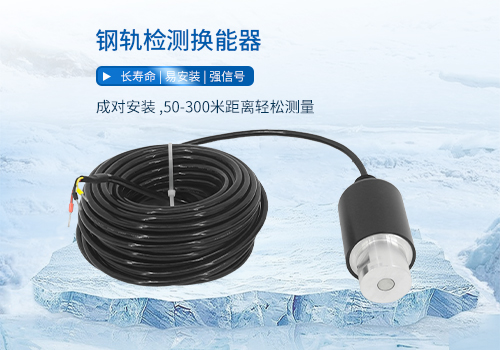
Special installation forms must be matched with dedicated inspection equipment, such as the wheel-type transducer assembly of a hand-pushed flaw detection trolley. This assembly integrates multiple transducers into a wheel-shaped coupling medium container, with transducers mounted on a bracket plane and angled surfaces, corresponding to refraction angles of 0°, 37°-45°, and 65°-75°, respectively, covering the entire cross-section of the rail head, rail web, and rail base in one pass. During installation, the bracket axis must be precisely connected to the trolley body to ensure that the transducers remain in contact with the rail surface throughout the inspection process.
In summary, the installation position of rail inspection transducers must be adapted to the rail cross-section structure, defect types, and inspection equipment. Through multi-position, multi-angle combined arrangements, full cross-section inspection without blind spots can be achieved, providing reliable technical support for the safe operation of rails.