
What Exactly Is the Emission Angle of an Ultrasonic Transducer? Three Diagrams to Save a Liberal Arts Student's IQ [Dayu Electronics]
Oh my goodness, as a liberal arts student, when I first heard the term "emission angle of an ultrasonic transducer," I almost rolled my eyes on the spot! The angle of ultrasonic waves? You can't see it with the naked eye, can't touch it, and can't hear it (since the frequency far exceeds 20kHz), so isn't this just metaphysics? Every time engineers discuss terms like "beam width" and "sharpness angle" with a serious face, I feel like an outsider—as if they're speaking Martian while I'm still stuck on ancient Chinese particles. Ultrasonic emission angle? Please, this is more abstract than quantum mechanics! It took me a full two weeks to barely grasp a tiny bit of it. Today, I'm here to vent about this "ghostly angle" and use the theories I've barely digested with my liberal arts brain to explain it to everyone. Don't worry, I'll try my best to use plain language, since I've just crawled out of "illiterate mode" myself.
First, we need to understand how an ultrasonic transducer works. Simply put, it's a "sound wave loudspeaker" that converts electrical signals into ultrasonic waves (sound with a frequency above 20kHz). The emission angle refers to the spread range of the ultrasonic beam emitted by this loudspeaker as it propagates through the air. Imagine playing with a laser pointer: if the laser beam is narrow, it can precisely hit a distant point; if it's wide, it spreads into a blurry spot.
Ultrasonic transducers work the same way—the emission angle determines whether the beam is "focused" into a thin line or "spread out" into a large fan shape. This angle directly affects detection accuracy: the smaller the angle, the more concentrated the beam, suitable for precise positioning (e.g., medical B-ultrasound to see fetal details); the larger the angle, the wider the coverage but with lower accuracy, suitable for large-area industrial detection (e.g., water level monitoring).
But why express it as an angle? Because the energy distribution of ultrasonic waves is not uniform! The energy is strongest at the center of the transducer and gradually attenuates toward the sides. Engineers use the unit "decibel (dB)" to quantify the degree of attenuation. What is a decibel? Simply put, it's a logarithmic scale used to express power changes (e.g., -3dB means the power is halved).
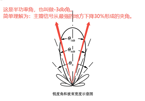
The emission angle is typically defined as the angular width at a specific attenuation point, such as the -3dB angle (half-power angle), which means the angle range where the power on both sides of the beam drops to 50% of the center maximum. This thing is crucial in acoustic theory—it affects the effective detection range, resolution, and sensitivity deviation of ultrasonic waves. For a practical example: in car reversing radar, if the emission angle is too large, ultrasonic waves will scatter randomly, causing false alarms; if it's too small, detection is incomplete, leading to safety hazards.
However, theory sounds impressive, but in reality, there are a bunch of "pitfalls." Ultrasonic propagation is also affected by the medium (such as air or water), frequency, and environmental interference. High-frequency transducers (e.g., 40kHz) typically have small emission angles, suitable for precise applications; low-frequency ones (e.g., 25kHz) have larger angles, providing wider coverage. But overall, the emission angle is a core parameter in transducer design—engineers rely on it to optimize performance and avoid "acoustic wave out of control."
How can a liberal arts student like me even understand what this sharpness angle and beam width are?
After all the theory, I'm still confused as a liberal arts student! Sharpness angle? Beam width? These terms sound like gibberish. Searching Baidu only returns formulas and charts, and my brain instantly explodes. Fortunately, I'm not fighting alone. To understand this emission angle, I consulted the book "Ultrasonic Handbook," which has a detailed introduction:
Directivity of transducers:
Transducers and transducer arrays' directivity refers to the characteristic that the amplitude of their transmitting response (voltage response and power response) or receiving response (sound pressure sensitivity or power sensitivity) varies with the azimuth angle. Typically, it has a maximum value in a certain reference direction. By plotting this directivity response in terms of its relative ratio, a directivity response diagram can be obtained. This diagram can be two-dimensional or three-dimensional; usually, it's two-dimensional.
The physical reason for the formation of directivity in transmitting transducers or transducer arrays is the result of interference and superposition of sound waves emitted by various parts of the transmitter in the far-field region of free space. Treating each point on the radiating surface as a point source, the sound waves produced by point sources are non-directional spherical waves. All these sub-waves superimpose with each other, and in the far field of the transmitting space, directivity is formed.
For receiving transducers or transducer arrays, the formation of directivity is because the sub-receiving transducer or array is in the far-field region of the sound source. The total force generated on the receiving array surface by the sound waves is the result of interference and superposition of each sub-wave. This total force varies with the incident angle of the incoming sound beam, and its open-circuit output voltage also varies with the incident angle of the incoming beam.
If all array elements of a transducer or transducer array are reciprocal transducers, it can be proven that the transmitting directivity pattern and the receiving directivity pattern of the transducer or array are identical.
Description of directivity parameters:
Sharpness angle
: refers to the angle between the first minima appearing on both sides of the main beam;
Beam width
: refers to the angle where the directivity function of the main beam drops to 0.707 (half-power point) of the main maximum on both sides;
There are also beam widths like 、
、 、
、 , etc.
Side lobe level: The normalized sound level of the maximum amplitude of the side lobes in the directivity pattern. For a transmitter, its magnitude reflects the proportion of total radiated energy in the side lobe direction; for a receiver, it reflects the amount of false target information in the side lobe direction.
Directional accuracy: A commonly used parameter in underwater acoustics. When the sound source gradually deviates from the direction of maximum value, the sound pressure value received by the detection equipment will also gradually decrease from the maximum. The minimum angle at which this decrease can be detected on the indicator is called the directional accuracy of the equipment,
denoted by , and its relationship with the directivity function is:

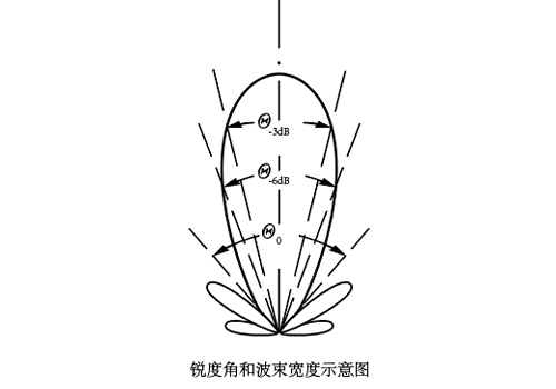
Diagram time: Three diagrams to save a liberal arts student's IQ.
First diagram: -3dB emission angle (also called half-power angle)
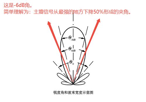
Second diagram: -6dB emission angle
Third diagram: Sharpness angle
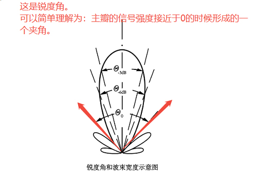
After all this fuss, I finally understood completely: although the ultrasonic emission angle is invisible and intangible, through dB attenuation and graphical visualization, it's actually quite "down-to-earth." The -3dB angle is the core energy zone, the -6dB angle is the diffusion boundary, and the sharpness angle is the focus precision—combining these three defines how ultrasonic waves "show off their skills" in the real world.