
Underwater Monitoring Marvel! Doppler Current Meter Installation Guide Revealed [Dayu Electronics]
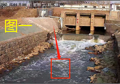
Doppler current meter is first installed underwater and should ideally remain submerged for extended periods. The installation point near the river or channel should have no branches, ensuring a relatively stable flow field. In Figure 1, the riverbed at the site has rubble piles and pebbles containing large boulders. If installation is required, a small concrete pier platform should first be constructed to secure the Doppler current meter. However, considering that opening the sluice gate for water release may carry debris that could collide with and damage the front sensor of the Doppler current meter, the DY68CDDZ radar flow meter is recommended. It employs DSP technology and advanced phyTrack fluid velocity detection and tracking algorithms, and features an embedded hydraulic flow model. This device adopts a compact structural design, with an IP68 waterproof and corrosion-resistant liquid housing, as well as convenient installation solutions.
Device features:
? Non-contact measurement of flow velocity, water level, and flow rate in partially filled pipes/open channels
? Integrated design, compact structure
? Adapts to various open channels, natural rivers, and partially filled pipes
? Rapid deployment, maintenance-free, long service life
? Automatically detects and determines flow direction
? Adapts to various flow conditions, capable of measuring weak flows and strong flows
? Unaffected by water quality or floating debris, no mechanical rotating parts
? Fast response, capable of measuring instantaneous flow and cumulative water volume
? Low power consumption, compatible with solar power systems
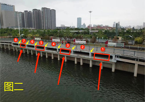
As shown in Figure 2, there are 8 drainage outlets, each free of debris. Conventionally, a Doppler current meter is installed at each of the 8 outlets, sharing one host computer processor. However, to reduce costs, 3-6 Doppler current meters can be installed across the 8 outlets, sharing a single host processor. Now, according to Figure 2, install 4 Doppler current meters at positions 1, 3, 5, and 7. From the yellow arrows in Figure 2, it can be seen that each outlet has a partition in the middle; the partition dimensions must be subtracted. Flow rate = velocity × cross-sectional area. Since accurate dimensions for the 8 outlets and the middle partitions are not available, an on-site survey is required.
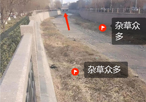
Figure 3: In urban river channels with dense vegetation on both banks, installing the ultrasonic Doppler current meter at the middle section would be affected. Once the water level rises, weeds and mud attach to the probe due to flow, and the support bracket would be long, leading to high maintenance in the long term. In the direction indicated by the red arrow in Figure 3, the meter should be installed at the bridge pier, where the fixing method is simple and secure. For fixed base installation, the base should be higher than the expected siltation thickness over a certain period, thus avoiding sediment accumulation.
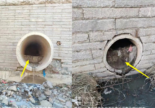
Figure 4: The upper two circular pipes have a partition, while the lower two do not. For the circular pipes with partitions, the partition structure needs modification. If it is an urban sewage discharge outlet, also check the amount of garbage and sediment. A small Doppler 0-degree current meter can be installed inside the pipe; the water level requirement is low, but it must be at least 5m above the sensor probe top.
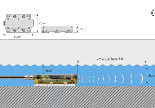
? Power supply: 10VDC~30VDC
? Flow velocity measurement range (water level must be at least 5m above the sensor top)
Positive flow: +0.03m/s~+5.00m/s
Negative flow: -1.00m/s~-0.3m/s (customizable range)
? Water depth measurement range: 0.02~3.00m, 0.02~10.00m
? Flow velocity accuracy: ±2~3% of measured velocity
? Water depth accuracy: ±5%
? Flow velocity resolution: 1mm/s
? Water depth resolution: 1mm
? Protection rating: IP68
? Cable length: 20m (other lengths customizable)