
Bridge Installation Guide: Highly Accurate Radar Water Level Measurement [Dayu Electronics]
1. Bridge Installation
1.1 Site Selection Requirements
The installation point should have an open, unobstructed view of the water surface, be far from bridge piers, and the river channel should be as straight as possible with no drops.
The choice of measurement location directly affects the accuracy of flow measurement. To achieve more accurate measurement results, the installation position should meet the following conditions as much as possible:
① The measurement location should be straight with stable water flow, no rocks blocking water, no large whirlpools, turbulence, or other such phenomena.
② The water flow at the measurement location should be concentrated with a stable channel width.
③ Hardening treatment is preferred, with a regular cross-section of the channel.
④ The water flow should be smooth, with no floating or suspended matter or other debris accumulation.
⑤ The installation position should be open with no obstructions around it.
⑥ Radar level meter should be installed with an extension outward.
⑦ Avoid high-voltage lines; do not install below high-voltage lines.
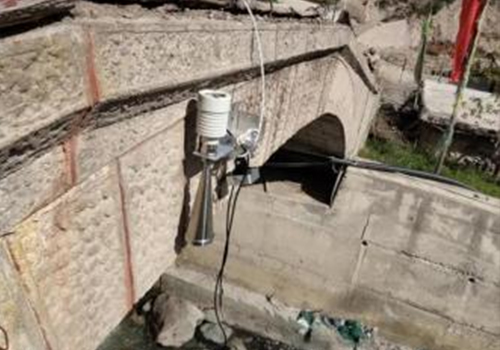
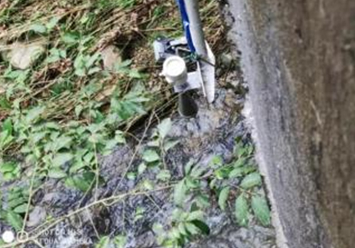
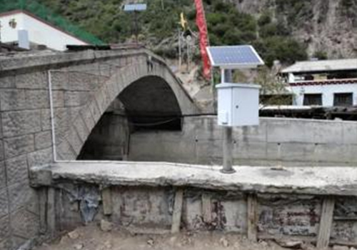
1.2 Example Installation Images on Bridge Sidewalls
1.3 Working Principle of the 80G FMCW Radar Level Meter
The general principle of the FMCW (Frequency Modulated Continuous Wave) radar level meter is that the radar emits electromagnetic waves from the top of the tank. When the waves hit the medium, they are reflected back and received by the radar. The frequency difference δf between the received signal and the transmitted signal is proportional to the distance R to the medium surface: R = C (speed) * δf (frequency difference) / 2 / K (frequency modulation slope). Since the speed of light C and the frequency modulation slope K are known, estimating the frequency difference δf allows the distance R from the radar installation position to the material surface to be obtained. Then, by subtracting the spatial distance from the radar to the material surface (referred to as empty height) from the known total height of the tank, the material level height is determined.
Features:
1. Millimeter-wave radar, with measurement accuracy up to ±2mm and a minimum blind zone of 0.1m.
2. Smaller antenna size, suitable for a wider range of industrial applications.
3. Multiple lens antennas with a smaller emission angle and more concentrated energy provide stronger echo signals, offering higher reliability compared to other radar products under the same working conditions.
4. Stronger penetration capability, allowing normal operation even with adhesion or condensation.
5. Wider dynamic signal range, providing more stable measurement for low dielectric constant media.
6. Multiple measurement modes; in fast measurement mode, the radar response time is less than 1 second.
Model: DY-HLS03 Installation Diagram
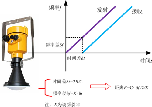
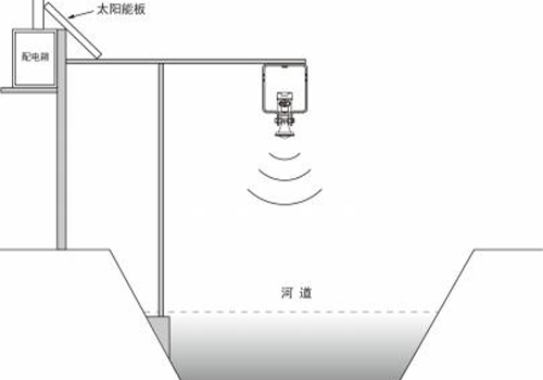
Note: When the radar antenna emits microwaves, there is always a certain emission angle. The area from the lower edge of the antenna to the surface of the medium being measured, as well as the region radiated by the microwave beam, must be free of obstacles. Therefore, during installation, avoid obstructions as much as possible, and if necessary, perform a "false echo learning" procedure. When installing the instrument, also note that the highest liquid level must not enter the measurement blind zone.
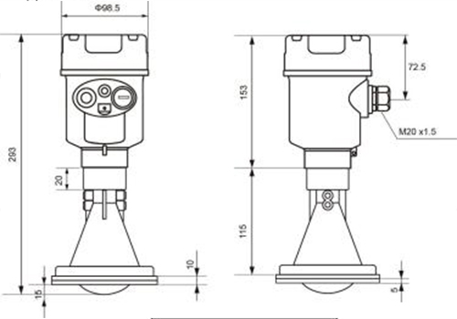
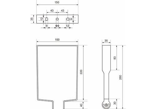
Product Dimensions (Unit: mm)
l Product Dimensions:
l Gantry Frame Dimensions:
Because the range is 200 meters, a water level circuit board cannot be used for 200 meters, so it must be changed to a level measurement circuit board. Output dual output: 4~20mA + RS485 for real-time monitoring. For fast response, it is not low power consumption.
Data is transmitted wirelessly to the backend platform. To reduce daily maintenance work, lower maintenance costs, reduce equipment failure rates, and improve effective usage time, it was decided to use a non-contact radar water level meter for measurement.