
DY-L-03D Radar Flow Meter Parameters Unveiled [Dayu Electronics]
1. Flow Meter Selection and Installation:
Channel flow meters primarily use the water level method or the velocity-area method:
1. The water level method measures the upstream (or upstream and downstream) water level of a water measuring structure and converts it to flow using empirical formulas or experimental curves. Therefore, this method requires the construction of structures, has limited accuracy, and may cause head loss which affects channel capacity when head differences are small. Additionally, if downstream structures like gates create submerged flow, measurement accuracy drops significantly.
2. The velocity-area method does not require water measuring structures. It calculates flow by measuring the cross-sectional area (obtained via water level measurement) and the cross-sectional velocity, offering high accuracy and immunity to downstream backwater effects.
The velocity-area method includes four main techniques:
Fixed ADCP method
Doppler ultrasonic method (longitudinal transmission)
Multi-path ultrasonic transit-time method
Non-contact radar current meter method
Given that the measured channel is a natural river with a width of 20 to 100 meters, and the flow rate is high, the current is swift, and the water is deep, the multi-path transit-time flow meter is not suitable. Doppler and radar flow meters are more appropriate. Considering the swift current and installation constraints, contact-type measurement is impractical. Therefore, a non-contact radar flow meter is selected, offering easy installation without stopping water flow, low subsequent maintenance, and high equipment safety.
1. Radar velocity flow meter: For open channels, simultaneously monitors water level, velocity, and flow.
2. Micro-power data acquisition and transmission unit: Comprises a data logger and NB or 4G communication module. The logger collects and stores flow meter data, transmitting it to the monitoring center via NB or 4G.
3. Monitoring and management software: Installed on a server, allowing authorized personnel to log in, query, and control from any location via the internet. The server requires a fixed IP.
The typical installation layout is shown below:
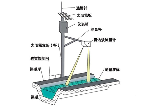
The radar velocity sensor is installed directly above the channel. Water level is measured with a radar level meter. The upper computer is integrated into the combined water level and velocity unit, and the remote transmission module is placed in a protective box on a pole. Monitored water level, velocity, and flow data are transmitted to the management server at the authority, allowing managers to access, analyze, and perform statistical processing online.
For wider channels, multiple velocity sensors can be used. The installation diagram is as follows:
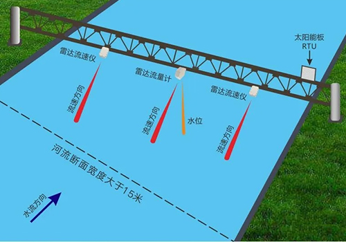
For water level measurement, either one radar level meter or one integrated water level/velocity unit (radar flow meter) can be configured. The remaining units are individual velocity meters. The cross-section does not need uniform distribution; it should be arranged based on the velocity profile to select representative measurement points.
2. Equipment:
Radar Flow Meter Parameters (Model DY-L-03D Integrated Radar Flow Meter)
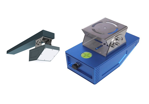
· Velocity:
· Range: 0.05 m/s to 30 m/s (dependent on flow conditions).
· Accuracy: ±2% of measured velocity.
· Resolution: 1 cm/s.
· Water Level:
· Range: 0.1 to 60 m.
· Resolution: 1 mm.
· Accuracy: ±1 cm (±0.5% of measured level).
· Flow:
· Accuracy: ±2% of measured flow.
· Power:
DC 7-28 V.
· Interface:
RS232, RS485.
· Communication Protocol:
Modbus-RTU.
· Transmission Frequency:
Velocity: 24 GHz; Water level: 60 GHz.
· Operating Temperature:
-30°C to 70°C (water temperature).
· Housing Material:
Galvanized and stainless steel.
· Ingress Protection Rating:
IP67.
· Reliability:
MTBF ≥ 25000 hours.
· Dimensions:
220 × 120 × 84 mm (sensor).
100 × 100 × 100 mm (mounting bracket).
Host (Telemetry Terminal Unit) Parameters
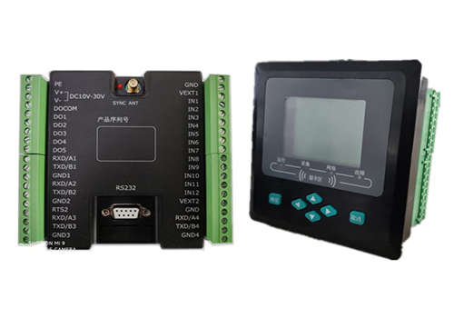
1) 12 input channels: Analog and digital inputs, freely configurable in quantity.
Analog input: Accepts standard 4-20 mA and 0-5 V signals.
Digital input: Optocoupler-isolated input board.
2) 2 VEXT outputs: Power supply for analog, digital, and serial instruments.
VEXT1: Provides 12 V DC.
VEXT2: Provides 5 V or 12 V DC.
3) 4 RS232/RS485 interfaces: Up to 4 serial instruments, freely configurable as RS232 or RS485. Serial 3 and 4 can be configured as pulse counter inputs if needed.
4) 1 DB9 debug port.
5) 1 Bluetooth wireless configuration (optional).
6) 5 relay outputs: Direct connection to contactors without intermediate relays.
DO1 contact rating: 16 A, 250 V AC
DO2-5 contact rating: 6 A, 250 V AC
7) 1 LCD or LED display, 6 push buttons.
8) 1 wireless communication port: 4G/3G/2G/NB-IoT optional.
9) Wireless IC card reader: Maximum read range 5 cm.
? Storage capacity: 4M, 8M, 16M, 32M (optional).
? Power supply: DC 10-30 V or AC 10-24 V; recommended AC 18 V, AC 12 V, DC 12 V, DC 24 V.
? Power consumption: Average standby current ≤ 13 mA at 12 V;
Average communication current ≤ 73 mA at 12 V.
? Operating environment: Temperature: -40 to +85°C; Humidity: ≤95%.
? Mounting: Panel-mount type.
? Dimensions: 120 × 120 × 65 mm.
3. Power Supply and Field Installation Recommendations:
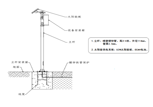
Since the radar flow monitoring equipment is installed in the field, solar power is used. The solar power system includes an 80W solar panel and a 30Ah lithium battery, ensuring continuous operation even during prolonged cloudy or rainy conditions.